 |
|||
|
|
|||
|
|
|||
| ||||||||||
|
|
 TM 5-2410-237-23
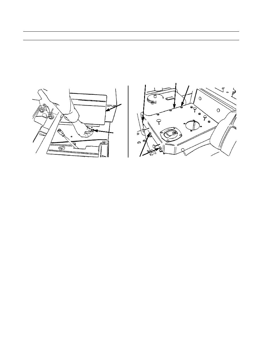
WINCH CONTROL LEVER AND LINKAGE REPLACEMENT - CONTINUED
0183 00
REMOVAL - CONTINUED
4.
Lift seat and remove two capscrews (9), washers (10) and armrest (11) from control console.
5.
Remove six capscrews (12) and washers (13), two capscrews (14) and washers (15) and capscrew (16) and washer (17)
that secure cover (18) to control console. Remove cover.
18
16,17
12,13
11
9,10
387-421
14,15
387-420
NOTE
Tag control cables to ensure proper installation.
6.
Remove capscrew (21) and self-locking nut (22) from control cable (19). Discard self-locking nut.
7.
Unscrew control cable (20) and remove lockwasher (23). Discard lockwasher.
8.
Remove nut (24) and washer (25) from bellcrank (26).
9.
Remove bellcrank (26) with lever (2) from bracket (27).
CAUTION
Drive spring pin through backside of block on lever to avoid damaging threads at front end of hole.
10.
Remove spring pin (28) from bellcrank (26). Discard spring pin.
11.
Remove shaft (29) and lever (2) from bellcrank (26).
12.
Remove two bushings (30) from bellcrank (26).
13.
Remove two bushings (31) from bracket (27).
14.
Remove bolt (32), two washers (33), nut (34) and two clamps (35) from control cables (19 and 20) and bracket (27).
15.
Remove four capscrews (36), lockwashers (37) and bracket (27). Discard lockwashers.
0183 00-2
|
|
Privacy Statement - Press Release - Copyright Information. - Contact Us |
