 |
|||
|
|
|||
|
|
|||
| ||||||||||
|
|
 TM 5-2410-237-23
WINCH THEORY OF OPERATION - CONTINUED
0178 00
WINCH MECHANICAL DESCRIPTION - CONTINUED
9.
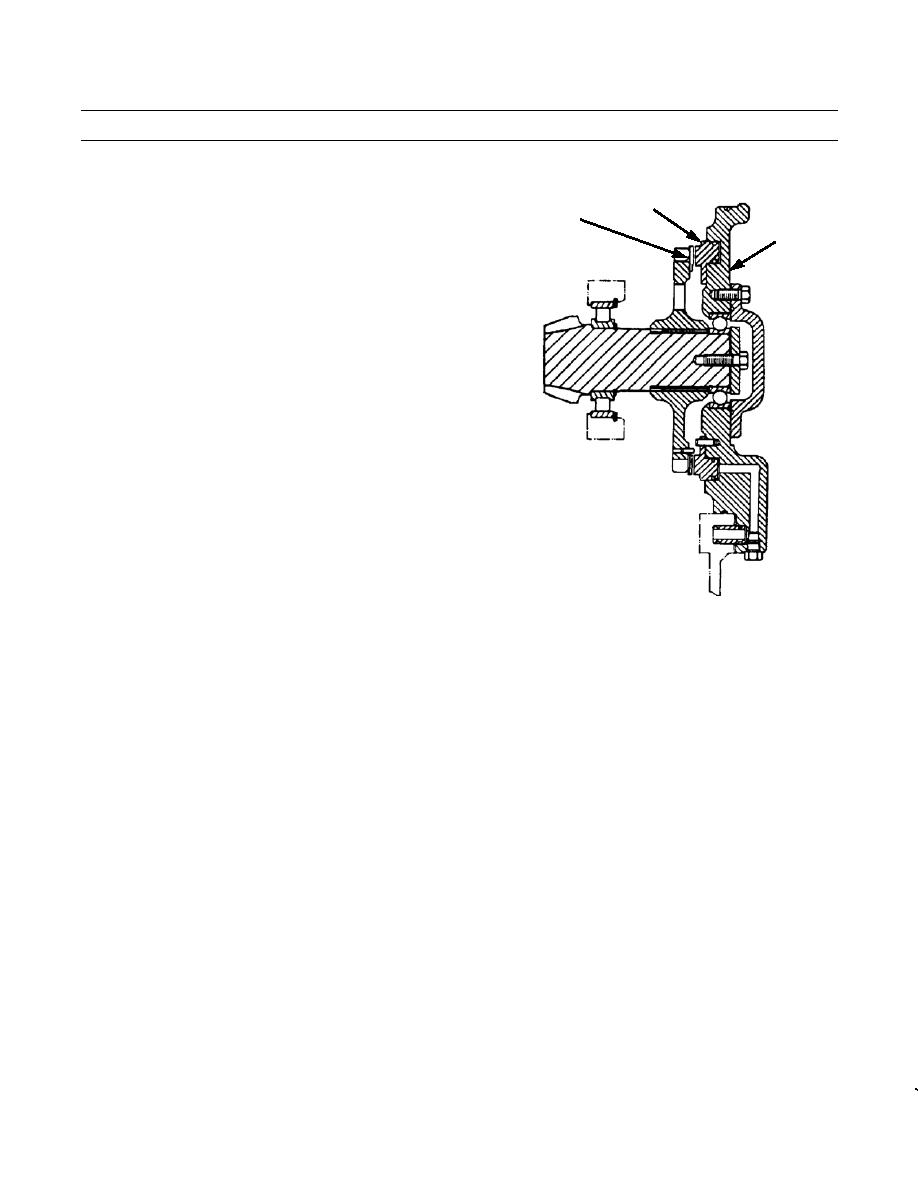
When the winch control lever is in the BRAKE ON
8
position, the viscous drag brake stops the winch from
9
spooling the cable in. A portion of the lube oil, which
7
is 32 psi (221 kPa) at low idle, is sent through mani-
fold (7) to piston (8). The force of the oil moves piston
(8) to the left against disc (9) which is pinned to gear.
The friction between the piston and disc is great
enough to prevent the viscous drag of the input clutch
from turning the bevel gear and shaft assembly.
387-536
WINCH HYDRAULIC SYSTEM
1.
The winch hydraulic system consists of a pump, a filter, a directional control valve, a pressure control valve and piping.
The system reservoir is located in the bottom of the winch case. The same hydraulic oil is used as lubricating oil for the
gearing, bearings and other moving parts of the winch.
2.
The winch control valve allows the winch to be placed in any of four conditions: 1) HOLD (Brake On); 2) REEL IN; 3)
REEL OUT; or 4) BRAKE OFF.
a. In the HOLD condition, both directional clutches are engaged. The input clutch is disengaged, disconnecting the
winch from the PTO. Engaging the two spring-applied directional clutches "locks up" the winch drive shaft and
keeps the winch from turning. In this condition, a load can be towed using the winch cable.
b. For either REEL IN or REEL OUT, the input clutch must be engaged and the appropriate directional clutch must
be disengaged. The opposite directional clutch remains engaged. Torque from the PTO shaft can then be transmit-
ted through the input clutch, transfer gearing, housing of the disengaged directional clutch, winch shaft, planetary
gearing and winch drive gears to the winch drum. Selecting the opposite direction of winch rotation, with the con-
trol valve, will cause the disengaged directional clutch to re-engage and the other directional clutch to disengage.
The input clutch remains engaged.
c. Placing the control valve in the BRAKE OFF position will establish an oil flow such that both directional clutches
are disengaged while the input clutch remains disengaged. In this condition, cable can be spooled off the winch
drum either by pulling the cable or by attaching the cable to an object and driving the tractor forward.
0178 00-2
|
|
Privacy Statement - Press Release - Copyright Information. - Contact Us |
