 |
|||
|
|
|||
|
|
|||
| ||||||||||
|
|
 TM 5-2410-237-23
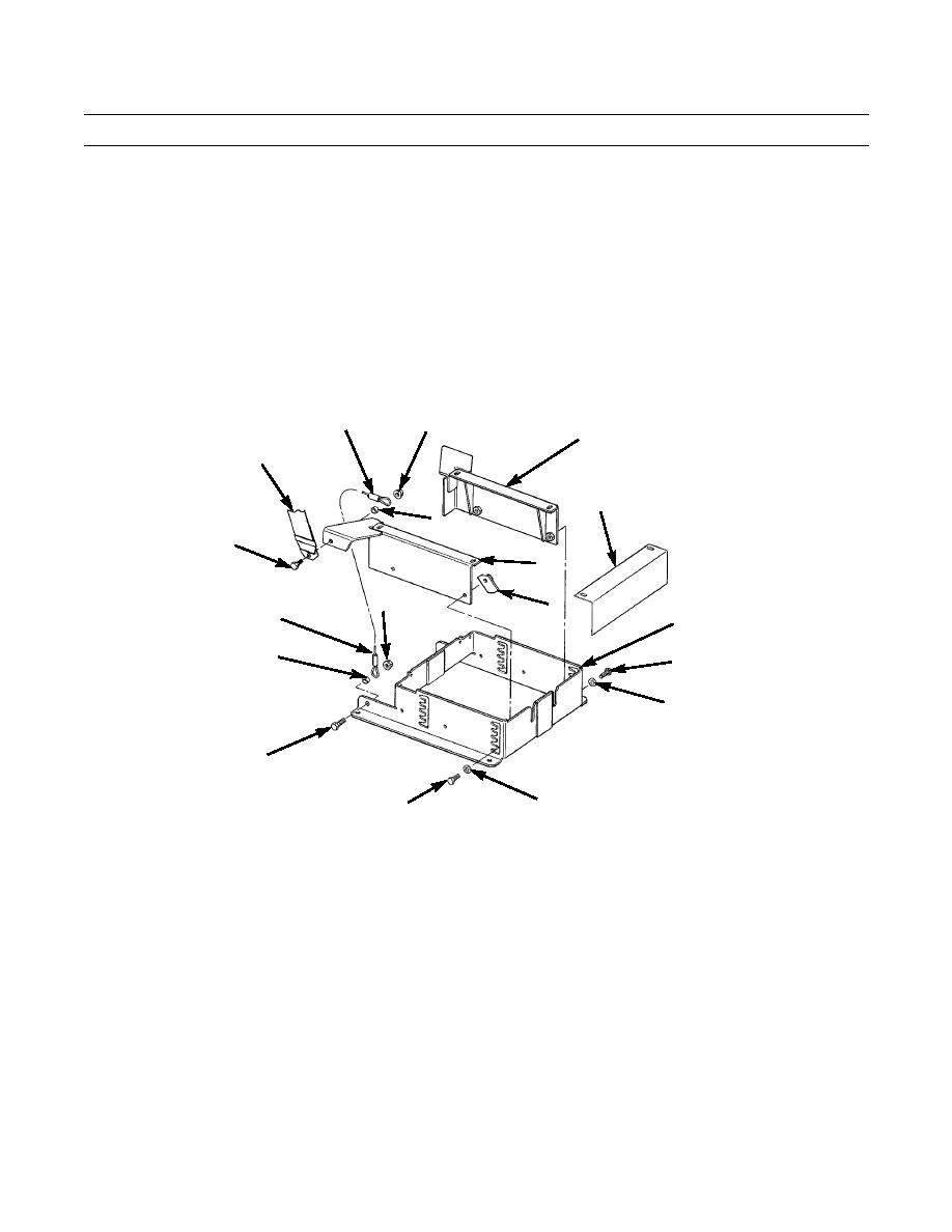
SEAT VERTICAL ADJUSTER MAINTENANCE - CONTINUED
0174 00
DISASSEMBLY
1.
Remove sheet (5) from front of base (6).
2.
Remove self-locking nut (7), spacer (8), capscrew (9) and end of cable (10) from back of base (6). Discard self-locking
nut.
3.
Remove self-locking nut (11), other end of cable (10), spacer (12), seat belt (13) and eyebolt (14) from R.H. support
(15). Discard self-locking nut.
4.
Repeat steps 2 and 3 for cable (10) and seat belt (13) on L.H. support (16).
5.
Remove two capscrews (17), washers (18), plate (19) and R.H. support (15) from base (6).
6.
Remove two capscrews (20), washers (21) and L.H. support (16) from base (6).
7.
Carefully inspect seat belt (13) for wear. Discard seat belt if wear is evident or if belt is 3 years old, as indicated on belt.
10
11
16
13
5
12
14
15
7
19
10
6
8
20
21
9
387-366
18
17
ASSEMBLY
NOTE
Always position L.H. and R.H. supports in lowest slots in base, unless directed otherwise.
1.
Position L.H. support (16) on base (6) and install two capscrews (20) and washers (21).
2.
Position R.H. support (15) on base (6) and install two capscrews (17), washers (18) and plate (19).
3.
Install seat belt (13) and one end of cable (10) on R.H. support (15) with eyebolt (14), spacer (12) and new self-locking
nut (11). Torque nut to 52 lb-ft (71 Nm).
4.
Install other end of cable (10) on back of base (6) with capscrew (9), spacer (8) and new self-locking nut (7). Torque nut
to 90 lb.-ft. (122 Nm).
5.
Repeat steps 3 and 4 for cable (10) and seat belt (13) on L.H. support (16).
6.
Install sheet (5) on front of base (6).
0174 00-2
|
|
Privacy Statement - Press Release - Copyright Information. - Contact Us |