 |
|||
|
|
|||
|
|
|||
| ||||||||||
|
|
 TM 5-2410-237-23
STEERING BRAKE HYDRAULIC CONTROL ASSEMBLY MAINTENANCE - CONTINUED
0151 00
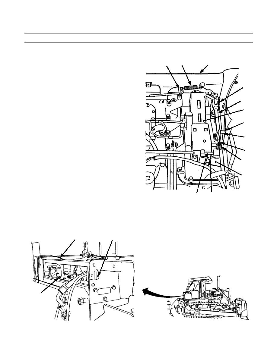
INSTALLATION - CONTINUED
26.
Install two links (18) to shaft assembly (19) with pin
7
3
8
(17) and new cotter pin (16).
27.
Install spring (13) between bracket (14) and lever (15)
on shaft assembly (19).
9,10
28.
Repeat steps 26 and 27 at other end of shaft assembly
(19).
11
29.
Install one end of brake control rod (11) on lever on
hydraulic control (12) with pin (10) and new cotter pin
12
(9).
15
30.
Repeat step 29 at other end of brake control rod (11).
13
18
16,17
14
31.
Position fender brace (3) between fenders.
387-705
20,21
32.
Secure center of fender brace (3) to frame with three
19
washers (6), new lockwashers (5) and capscrews (4).
33.
Secure one end of fender brace (3) to fender with three
new lockwashers (2) and capscrews (1).
34.
Repeat step 33 at other end of fender brace (2).
35.
Install spring (7) on fender brace (3) and fuel shut-off lever (8).
3
1,2
4,5,6
387-704
0151 00-19
|
|
Privacy Statement - Press Release - Copyright Information. - Contact Us |
