 |
|||
|
|
|||
|
|
|||
| ||||||||||
|
|
 TM 5-2410-237-23
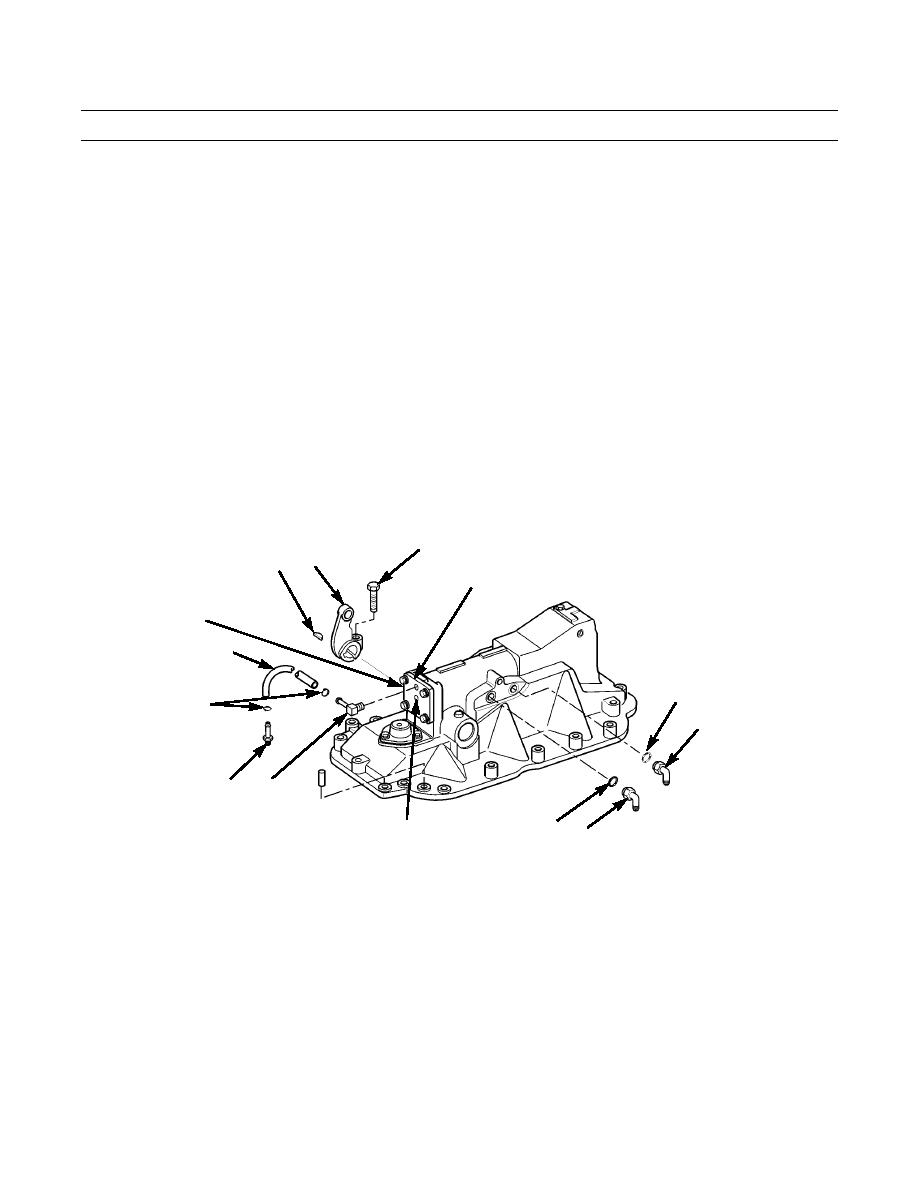
STEERING BRAKE HYDRAULIC CONTROL ASSEMBLY MAINTENANCE - CONTINUED
0151 00
ASSEMBLY - CONTINUED
28.
Force lever (62) open for assembly.
29.
Install key (63) in shaft (64).
30.
Align slot in lever (62) with key (63), slide lever on key and shaft (64), centering lever over key. Remove tool from
lever.
31.
Install capscrew (61) in lever (62).
32.
Push on lever (62) to put pressure on springs inside hydraulic control (12) and remove capscrew wedged between
plunger assembly (65) and housing. Slowly release pressure on lever until plunger assembly bottoms on roller (75) and
cover (57).
33.
Apply a light film of clean lubricating oil to two new O-rings (60) and install O-rings on elbows (59).
34.
Install two elbows (59) in side of hydraulic control (12).
35.
Install hose fitting (58) in hydraulic control (12) and elbow (56) in cover (57).
36.
Install hose (55) on elbow (56) and hose fitting (58) and secure with two hose clamps (54).
61
62
63
57
64 (HIDDEN)
55
60
54
59
56
58
387-711
60 59
65 (HIDDEN)
INSTALLATION
CAUTION
Care should be taken not to contaminate steering brake system during installation of hydraulic lines. Dirt
and foreign substances should be removed from surrounding area before lines are installed.
NOTE
This procedure is to be used for either R.H. or L.H. steering brake hydraulic control assembly.
1.
Install two lifting links (53) with 1/2-13 x 1-1/2 in. bolts, one at each end of hydraulic control (12).
0151 00-14
|
|
Privacy Statement - Press Release - Copyright Information. - Contact Us |
