 |
|||
|
|
|||
|
|
|||
| ||||||||||
|
|
 TM 5-2410-237-23
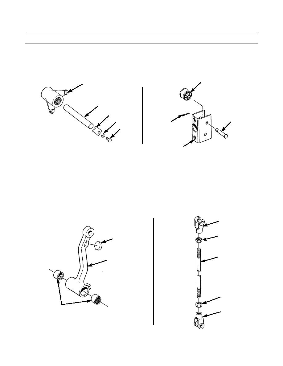
STEERING CLUTCH LEVERS AND LINKAGE MAINTENANCE - CONTINUED
0148 00
REMOVAL - CONTINUED
14.
Remove capscrew (36), lockwasher (37) and lock (38) from bellcrank shaft support bracket. Discard lockwasher.
15.
Pull shaft (39) out far enough to remove clutch linkage bellcrank (19) and reinsert shaft (39) into support bracket to
secure brake linkage bellcrank.
42
19
39
38
41
37
40
36
387-401
387-400
14
DISASSEMBLY
NOTE
Disassemble only as needed to replace damaged components.
1.
Remove cotter pin (40), pin (41) and roller (42) from bracket (14). Discard cotter pin.
2.
Repeat step 1 for other roller (42) in bracket (14).
3.
Remove bumper (43) and two bearings (44) from lever (18).
4.
Loosen two nuts (45) on rod (17) and remove two rod ends (46) and nuts.
46
45
43
17
18
45
44
46
387-402
387-403
0148 00-4
|
|
Privacy Statement - Press Release - Copyright Information. - Contact Us |
