 |
|||
|
|
|||
|
|
|||
| ||||||||||
|
|
 TM 5-2410-237-23
STEERING BRAKE PEDALS AND LINKAGE MAINTENANCE - CONTINUED
0146 00
DISASSEMBLY - CONTINUED
5.
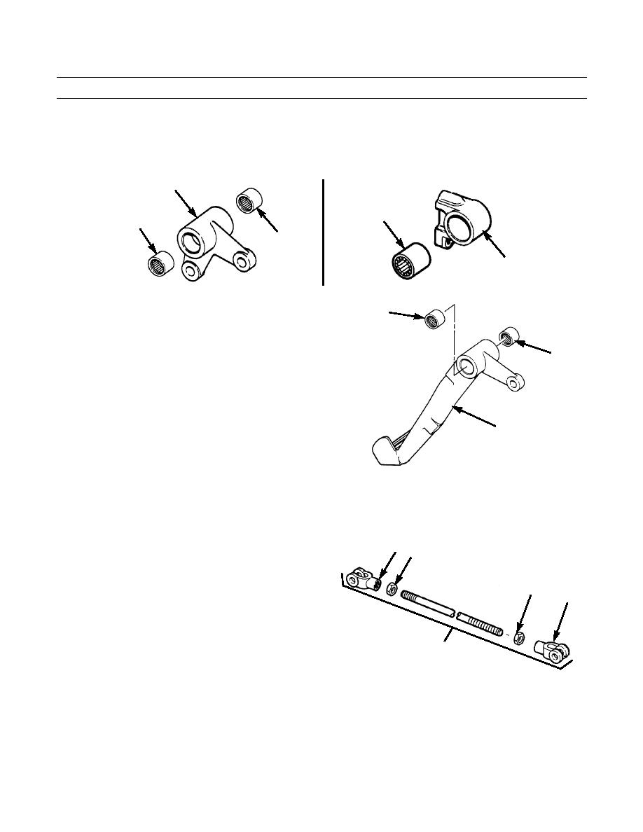
Remove two bearings (38) from bellcrank (10).
6.
Remove bearings (39) from shaft mounting bracket (29).
7.
Repeat step 6 for other bracket (29).
10
39
38
38
29
387-342
387-341
ASSEMBLY
37
1.
Install bearing (39) in shaft mounting bracket (29).
2.
Repeat step 1 for other bracket (29).
3.
Install two bearings (38) in bellcrank (10).
37
4.
Install two bearings (37) in foot pedal (17).
17
387-340
5.
Install nut (35) on each end of rod (13).
6.
Install rod end (36) on each end of rod (13). Adjust rod ends to a distance of 19.25 in. +/- 0.02 in. (48.90 cm +/- 0.51 cm)
between center lines of holes in rod ends.
7.
Tighten nuts (35) against rod ends (36) to 75 lb-ft (102
36 35
Nm).
8.
Repeat steps 5 through 7 for rod assembly (8). Ensure
that distance between center lines is 12.88 in. (32.72
35
36
cm).
9.
Install nut (35) and rod end (36) on each end of rod
(25). Do NOT tighten nuts at this time.
8,13,25
387-339
0146 00-4
|
|
Privacy Statement - Press Release - Copyright Information. - Contact Us |