 |
|||
|
|
|||
|
|
|||
| ||||||||||
|
|
 TM 5-2410-237-23
FINAL DRIVE PINIONS AND FLANGES MAINTENANCE - CONTINUED
0126 00
DISASSEMBLY - CONTINUED
12
10.
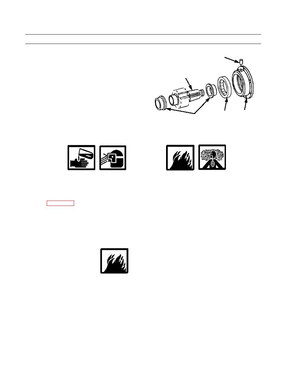
Install #10-32 screw in dowel (12) and pull on screw
to remove dowel from bearing cage (4). Remove
6
screw from dowel.
11.
Remove race and roller assembly (13) from bearing
cage (4).
12.
Remove bearing race (14) from one end of final drive
pinion (6) shaft.
387-780
13
4
14
13.
Repeat step 12 at other end of final drive pinion (6)
shaft.
CLEANING AND INSPECTION
WARNING
Solvent cleaning compound MIL-PRF-680 Type III is an environmentally compliant and low toxic mate-
rial. However, it may be irritating to the eyes and skin. Use of protective gloves and goggles. Use in well-ven-
tilated areas. Keep away from open flames and other sources of ignition.
1.
Clean all parts with solvent cleaning compound.
2.
Refer to WP 0241 00 for general inspection instructions.
3.
Refer to TM 9-214 for inspection of roller bearing.
4.
Replace damaged parts as necessary.
5.
Remove gasket material and clean all mating surfaces before assembly or installation.
ASSEMBLY
WARNING
Wear hand protection when handling hot components to prevent serious burns.
Heat two bearing races (14) to a maximum temperature of 275F (135C) and install one race at each end of final drive
1.
pinion (6) shaft. Races must contact shoulders on final drive pinion shaft.
2.
Allow bearing races (14) to cool and install roller assembly (13) in bearing cage (4) with hole in outer race in line with
dowel hole in cage.
3.
Use a #10-32 screw to install dowel (12) in bearing cage (4), to secure bearing race (14) and roller assembly (13).
Remove screw from dowel.
4.
Install bearing cage (4) on spline end of final drive pinion (6) shaft with flange toward splines.
0126 00-4
|
|
Privacy Statement - Press Release - Copyright Information. - Contact Us |