 |
|||
|
|
|||
|
|
|||
| ||||||||||
|
|
 TM 5-2410-237-23
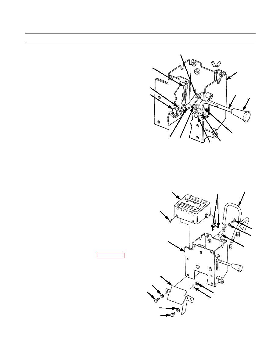
TRANSMISSION SAFETY LOCK LEVER REPLACEMENT - CONTINUED
0105 00
REMOVAL - CONTINUED
20
8.
Remove spring (14).
14
9.
Remove two cotter pins (15), washers (16) and rod
6
(17). Discard cotter pins.
10.
Remove two capscrews (18), lockwashers (19) and
lever (20) from transmission control box (6). Discard
19
lockwashers.
22
18
21
11.
Remove knob (21) from lever (22).
12.
Remove cotter pin (23), washer (24), lever (22),
spacer (25) and pin (26) from transmission control box
(6). Discard cotter pin.
23,24
17
15,16
25
26
387-368
INSTALLATION
1.
Position pin (26) and spacer (25) in transmission control box (6) and install lever (22), washer (24) and new cotter pin
(23).
2.
Install knob (21) onto lever (22).
3.
Install lever (20) in transmission control box (6) with
3
5
7
two new lockwashers (19) and capscrews (18).
4.
Install rod (17) with two washers (16) and new cotter
pins (15).
4
5.
Install spring (14).
6.
Position shield (12) on transmission control box (6)
and install capscrew (13), washer (9), new lockwasher
1
(10) and nut (11) on one side shield.
2
6
7.
Install capscrew (8), washer (9), new lockwasher (10)
7
and nut (11) on other side of shield (12).
8.
Install transmission selector lever (WP 0104 00).
9.
Connect two wires (7) and position guide cover (5) on
transmission control box (6).
12
10.
Secure guide cover (5) with four screws (4).
9
11.
Install knob on transmission selector lever.
8
12.
Install guard (3) with three new lockwashers (2) and
11
capscrews (1).
10
13.
Check transmission safety lock lever for proper opera-
9
tion.
13
387-367
END OF WORK PACKAGE
0105 00-2
|
|
Privacy Statement - Press Release - Copyright Information. - Contact Us |