 |
|||
|
|
|||
|
|
|||
| ||||||||||
|
|
 TM 5-2410-237-23
TRANSMISSION SELECTOR LEVER AND LINKAGE MAINTENANCE - CONTINUED
0104 00
ADJUSTMENT - CONTINUED
3.
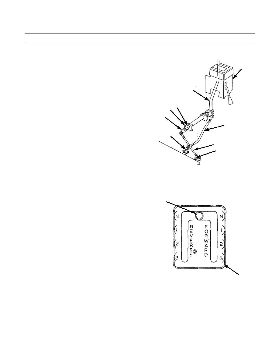
Disconnect rod assembly (26) from lever (27) and
selector lever (32). See Removal, steps 8 and 9.
5
4.
Put lever (27) in FORWARD "F" detent.
5.
Disconnect rod assembly (8) from levers (9 and 13).
See Removal, steps 4 and 5.
32
6.
Put lever (9) in NEUTRAL "N" detent.
21 24
13
26
27
8
9
387-522
7.
Put selector lever (32) in center of NEUTRAL open-
ing of guide cover (5).
32
387-524
5
8.
Adjust rod ends of rod assembly (8) until rod assembly can be installed between levers (9 and 13).
9.
Connect rod assembly (8) to levers (9 and 13). See Installation, steps 13 and 14.
0104 00-8
|
|
Privacy Statement - Press Release - Copyright Information. - Contact Us |