 |
|||
|
|
|||
|
|
|||
| ||||||||||
|
|
 TM 5-2410-237-23
GOVERNOR CONTROLS AND LINKAGE MAINTENANCE - CONTINUED
0058 00
REMOVAL - CONTINUED
38.
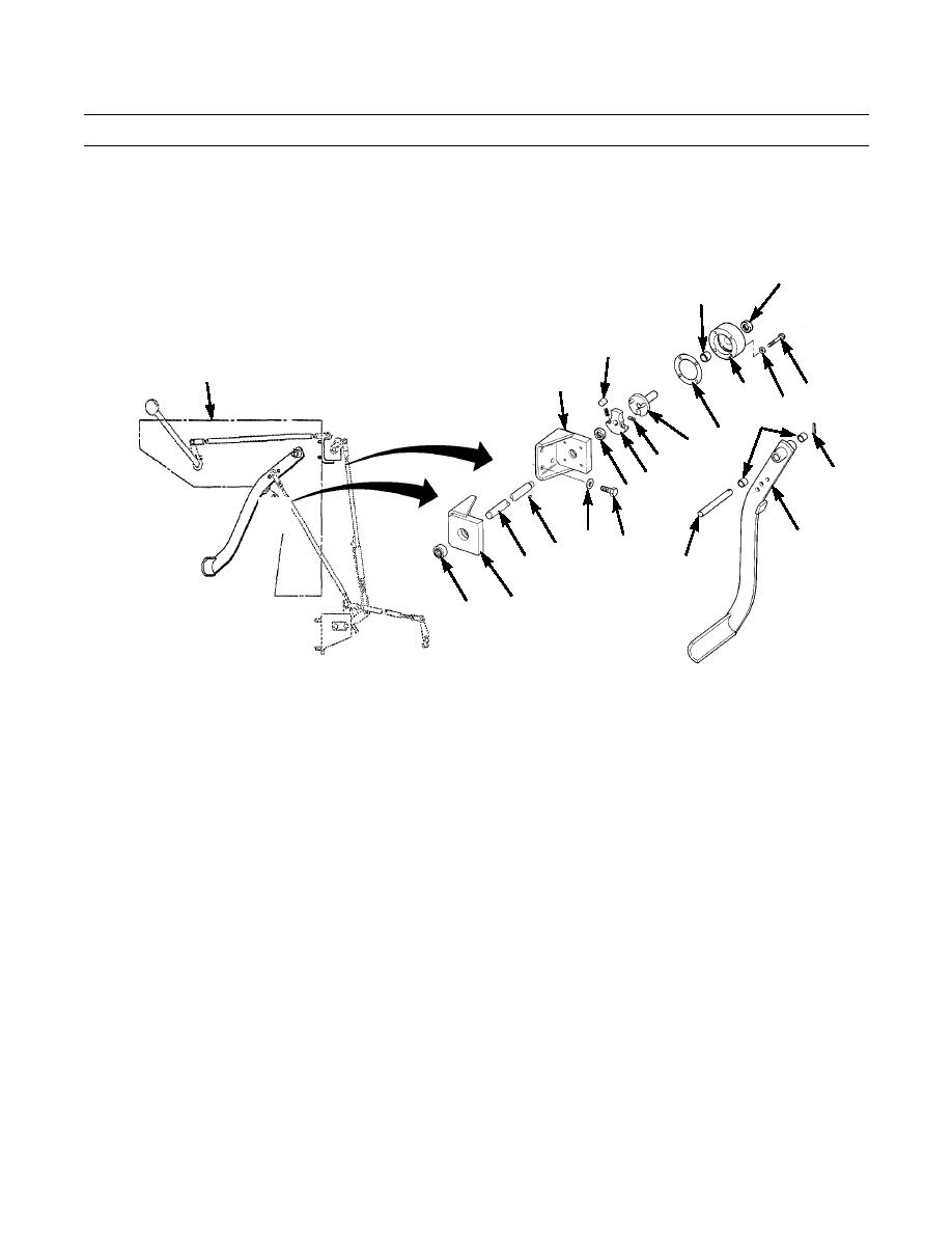
Remove two capscrews (79), washers (80) and support assembly (83) from back of dash assembly.
39.
Remove bearing (84) from support assembly (83).
40.
Remove pin (85) from dowel (86). Slide decelerator pedal (23) off dowel. Remove bearings (87) from pedal.
77
78
72
5
81
70
68
69
87
76 71
73
DASH
85
74
AREA
82
DASH
ASSY
80
23
79
75
86
34
83
84
MOUNTED ON
FLYWHEEL
HOUSING
MOUNTED ON
GOVERNOR
387-429
INSTALLATION
NOTE
Use a lint-free rag to wipe contact surfaces of all moving parts clean prior to installation.
Drive small chisel into slot in levers to open them up for installation on shafts.
1.
Install bearings (87) in decelerator pedal (23). Position pedal on dowel (86) and install pin (85) to keep assembly secure.
2.
Install bearing (84) in support assembly (83).
3.
Install support assembly (83) on back of dash assembly (5) with two capscrews (79) and washers (80).
4.
Lubricate sealing lip and install new seal (82) in support assembly (81).
5.
Install support assembly (81) on back of dash assembly (5) with four capscrews (79) and washers (80).
6.
Install bearing (78) in cover (70). Lubricate sealing lip and install new seal (77) in cover.
7.
Install key (75) and plate (74) on shaft (34).
8.
Lubricate cover (70).
9.
Install short shaft (76) in cover (70).
10.
Install two springs (73), rollers (72) and plate (74) end of shaft assembly in cover (70).
11.
Place new gasket (71) over shaft (34) and insert shaft through support assemblies (81 and 83).
12.
Align screw holes in cover (70), gasket (71) and support (81). Install four capscrews (68) and washers (69) to secure
cover (70).
0058 00-6
|
|
Privacy Statement - Press Release - Copyright Information. - Contact Us |