 |
|||
|
|
|||
|
Page Title:
GOVERNOR ADJUSTMENT |
|
||
| ||||||||||
|
|
 TM 5-2410-237-23
FUEL INJECTION PUMP AND GOVERNOR TIMING AND ADJUSTMENT - CONTINUED
0057 00
GOVERNOR ADJUSTMENT
NOTE
To perform these adjustments, governor and fuel injector pump housing is installed on engine and
engine is at operating temperature.
Engine low idle speed should be 670 +/- 30 RPM.
Engine high idle speed should be 2100 +/- 30 RPM.
Engine loaded rate should be 2000 +/- 10 RPM.
1.
Governor Low Idle Adjustment.
a.
Install photo tachometer and check engine low and high RPM on engine. Task complete if RPM is correct. If RPM
fails specification, continue with governor adjustments.
b.
Disconnect governor control linkage (WP 0058
c.
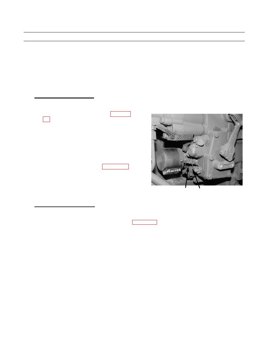
Adjust engine low idle RPM. Loosen locknut
(10) for low idle screw (11). Turn idle screw to
get correct low idle RPM.
d.
Increase engine speed and return to low idle and
check low idle speed again. Hold idle screw (11)
and tighten locknut (10) if low idle RPM is cor-
rect.
e.
Connect governor control linkage (WP 0058 00).
f.
Operate machine and check for proper operation
(TM 5-2410-237-10).
387-851
11
10
.
2.
Governor High Idle Adjustment.
NOTE
If engine does not achieve 2100 RPM, refer to WP 0058 00 to adjust governor control linkage.
END OF WORK PACKAGE
0057 00-4
|
|
Privacy Statement - Press Release - Copyright Information. - Contact Us |
