 |
|||
|
|
|||
|
|
|||
| ||||||||||
|
|
 TM 5-2410-237-23
ENGINE ASSEMBLY REPLACEMENT - CONTINUED
0021 00
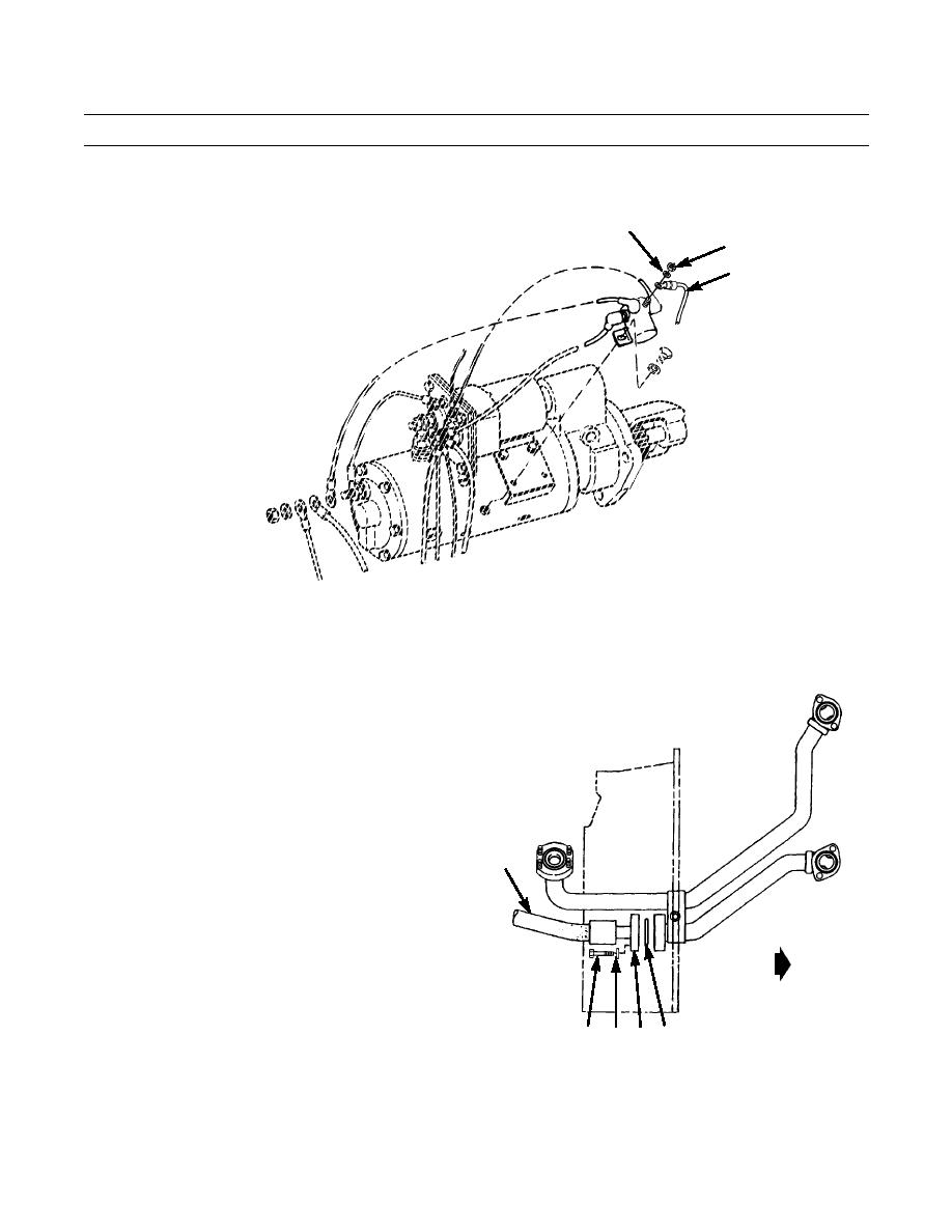
REMOVAL - CONTINUED
9.
Slide rubber boot from starter relay terminal. Remove nut (18) and washer (19) holding wire (20) to relay.
19
18
20
387-075
CAUTION
Wipe area clean around all hydraulic connections to be opened during removal. Cap oil lines and plug
openings after removing lines. Contamination of hydraulic system could result in premature failure.
NOTE
TO TRANSMISSION
OIL COOLER
If more than one hydraulic line is to
be removed, tag lines to ensure cor-
rect installation.
Use a suitable container to catch any
hydraulic oil that may drain from sys-
TO OUTLET
tem. Dispose of oil IAW local policy
and ordinances. Ensure all spills are
CONVERTER
cleaned up.
21
10.
Disconnect hose assembly (21) by removing four cap-
screws (22), washers (23) and two flange halves (24)
TO TRANSMISSION
holding hose assembly to oil cooler tube assembly.
OIL COOLER
Remove and discard O-ring (25).
TO
TRANSMISSION
FRONT
387-076
22 23 24 25
0021 00-4
Change 1
|
|
Privacy Statement - Press Release - Copyright Information. - Contact Us |
