 |
|||
|
|
|||
|
Page Title:
MACHINE AND RIPPER HYDRAULIC SYSTEM |
|
||
| ||||||||||
|
|
 TM 5-2410-237-23
THEORY OF OPERATION - CONTINUED
0003 00
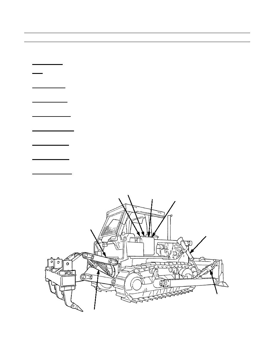
MACHINE AND RIPPER HYDRAULIC SYSTEM
1.
Hydraulic Tank. Provides containment for the oil which flows through the pilot and main hydraulic systems.
Filter. Removes harmful particles from the hydraulic oil before they can enter the system. It is located in the hydraulic
2.
tank.
3.
Blade Pilot Valve. Actuates the blade control valve for blade tilt. The blade pilot valve is actuated mechanically by the
blade tilt control lever and linkages.
4.
Ripper Pilot Valve. Actuates the ripper control valve for ripper lift. The ripper pilot valve is actuated mechanically by the
ripper lift control lever and linkages.
Blade Control Valve. Controls oil going to cylinders for blade tilt and lift. Blade tilt is hydraulically actuated by the blade
5.
pilot valve, and blade lift is mechanically activated by the blade lift control lever and linkages.
6.
Ripper Control Valve. Controls oil going to cylinders for ripper lift. Ripper lift is hydraulically actuated by the ripper
pilot valve.
Blade Tilt Cylinder. Activated when the blade tilt control lever actuates the pilot valve and sends pressure oil through the
7.
control valve to the tilt cylinder.
8.
Blade Lift Cylinder. Activated when the blade control lever actuates the control valve and sends pressurized oil to the lift
cylinders.
Ripper Lift Cylinder. Activated when the ripper control lever actuates the pilot valve and sends pressurized oil through
9.
the ripper control valve to the lift cylinders.
HYDRAULIC
TANK
PILOT VALVES
BLADE CONTROL VALVE
FILTER
(BEHIND TANK)
(BEHIND TANK)
RIPPER
CONTROL VALVE
BLADE LIFT
CYLINDER
BLADE TILT
CYLINDER
RIPPER LIFT
387-057
CYLINDER
0003 00-10
|
|
Privacy Statement - Press Release - Copyright Information. - Contact Us |