 |
|||
|
|
|||
|
|
|||
| ||||||||||
|
|
 TM 5-2410-233-23
BLADE DIAGONAL (ADJUSTABLE) BRACE REPLACEMENT - CONTINUED
0171 00
REMOVAL
NOTE
Blade diagonal brace weighs 91 lb (41 kg).
1.
Attach a nylon sling and a suitable lifting device to brace (1).
2.
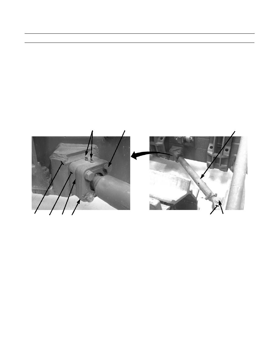
Remove cotter pin (2), pin (3) and pin (4) from brace (1) and pusharm (5). Lower brace and rest on ground. Discard cot-
ter pin.
3.
Adjust sling and lifting device to support blade end of brace (1).
4.
Remove four bolts (6), lockwashers (7), ball joint socket (8), shims, (9) and ball joint socket (10) from weldment (11) on
blade. Discard lockwashers.
5.
Use nylon sling and lifting device to remove brace (1).
6.
If ball joint (8) needs replacing, brace (1) must be disassembled.
12
6,7
1
386-528
2,3,4
5
11
10
8
9
INSTALLATION
NOTE
Blade diagonal brace weighs 91 lb (41 kg).
1.
Attach a nylon sling and a suitable lifting device to brace (1) and position brace at pusharm (5).
2.
Install brace (1) to pusharm (5) with pin (4), pin (3) and new cotter pin (2).
3.
Adjust sling and lifting device to support and position other end of brace (1) at weldment (11) on blade.
4.
Install brace (1) and ball joint sockets (8 and 10) to weldment (11) with four bolts (6). Do NOT install lockwashers (7)
or shims (9).
5.
Measure gap between ball joint sockets (8 and 10) without shims (9).
6.
Remove four bolts (6) and install shims (9) equal to measured gap plus ONE shim.
7.
Install four new lockwashers (7) and bolts (6).
8.
Apply GAA grease to ball and socket grease fittings (12).
9.
Operate machine and check for proper operation (TM 5-2410-233-10).
END OF WORK PACKAGE
0171 00-2
|
|
Privacy Statement - Press Release - Copyright Information. - Contact Us |