 |
|||
|
|
|||
|
|
|||
| ||||||||||
|
|
 TM 5-2410-233-23
RIPPER CONTROL LEVER AND LINKAGE REPLACEMENT- CONTINUED
0152 00
REMOVAL
1.
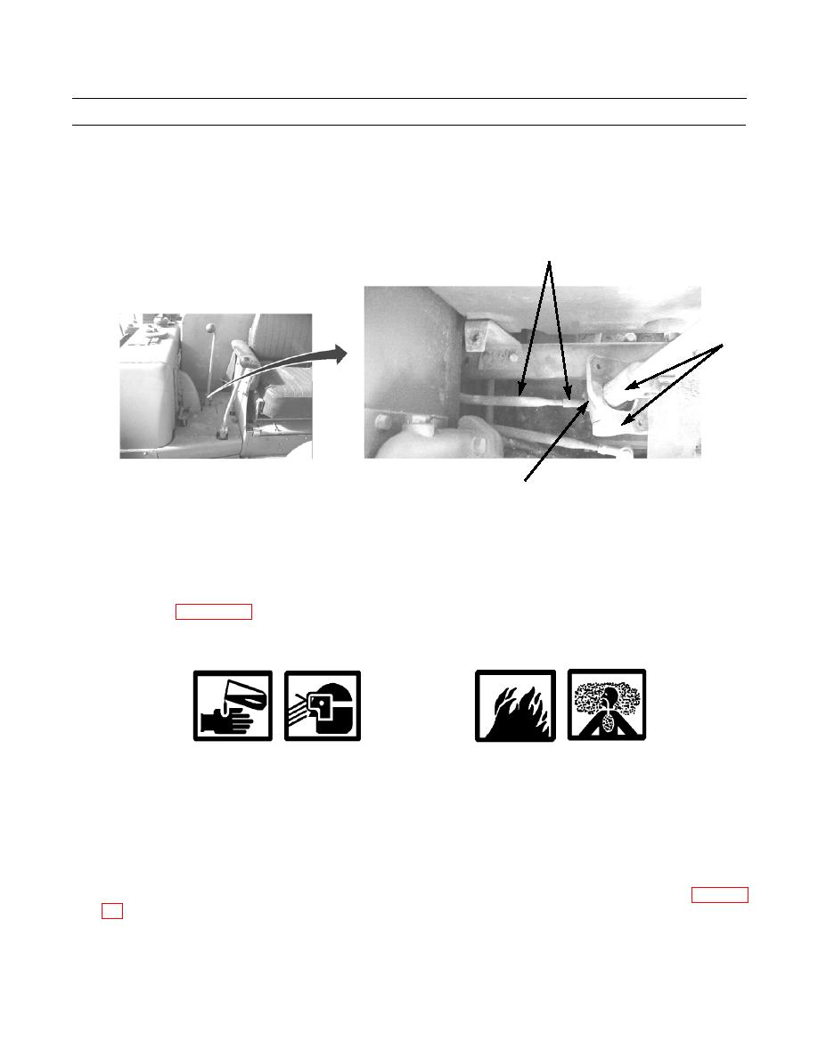
Remove nut (1) and bolt (2) from ripper control lever linkage (3) and bell crank (4).
2.
Remove ripper control lever assembly (5).
3
5
386-774
1,2,4 (HIDDEN)
NOTE
Ripper control linkage is connected to ripper control valve under hydraulic tank.
3.
To remove ripper control lever linkage (3) from ripper control valve lever under hydraulic tank, refer to Hydraulic Tank
CLEANING AND INSPECTION
WARNING
Solvent cleaning compound MIL-PRF-680 Type III is an environmentally compliant and low toxic mate-
rial. However, it may be irritating to the eyes and skin. Use protective gloves and goggles. Use in well-venti-
lated areas. Keep away from open flames and other sources of ignition.
1.
Clean all parts of control linkage with solvent cleaning compound and dry rags.
2.
Inspect all parts and replace any damaged items. Refer to TM 5-2410-233-23P for required replacement parts.
INSTALLATION
1.
If removed, install ripper control lever linkage (3) to ripper control valve lever located under hydraulic tank (WP 0166
2.
Position ripper control lever linkage (3) to bell crank (4) and install bolt (2) and nut (1) to ripper control lever assembly
(5).
0153 00-2
|
|
Privacy Statement - Press Release - Copyright Information. - Contact Us |
