 |
|||
|
|
|||
|
Page Title:
RIPPER CONTROL VALVE REMOVAL - CONTINUED |
|
||
| ||||||||||
|
|
 TM 5-2410-233-23
MAIN (BULLDOZER) CONTROL VALVE, RIPPER CONTROL VALVE
AND RELIEF VALVE REPLACEMENT - CONTINUED
0151 00
RIPPER CONTROL VALVE REMOVAL - CONTINUED
8.
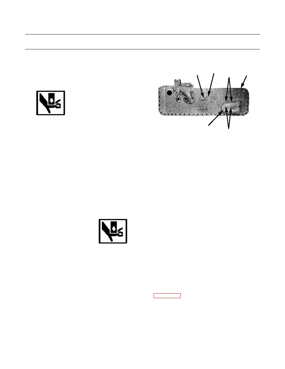
Remove four bolts (42) and lockwashers (43) securing
42,43
44
8
45,46
lever group (44) to bottom plate (8). Discard lock-
washers.
WARNING
386-739
Use extreme caution when handling heavy
parts. Provide adequate support and use assis-
47,48
tance during procedure. Failure to follow this
45,46
warning may result in injury.
NOTE
Ripper control valve weighs 50 lb (23 kg).
9.
Remove four bolts (45) and lockwashers (46) that
mount ripper control valve (30) and manifold (47) to
bottom plate (8). With assistance, remove valve and
manifold from bottom plate. Remove and discard two
O-rings (48).
RIPPER CONTROL VALVE INSTALLATION
WARNING
Use extreme caution when handling heavy parts. Provide adequate support and use assistance during pro-
cedure. Failure to follow this warning may result in injury.
NOTE
Ripper control valve weighs 50 lb (23 kg).
NOTE
Apply sealing compound to control valve mounting bolts before installation.
Lightly coat new O-rings with clean oil before installation.
1.
Position ripper control valve (30), two new O-rings (48) and manifold (47) on bottom plate (8) and secure with four new
lockwashers (46) and bolts (45).
2.
Position lever group (44) on bottom plate (8). Secure with four new lockwashers (43) and bolts (42).
0151 00-10
|
|
Privacy Statement - Press Release - Copyright Information. - Contact Us |