 |
|||
|
|
|||
|
|
|||
| ||||||||||
|
|
 TM 5-2410-233-23
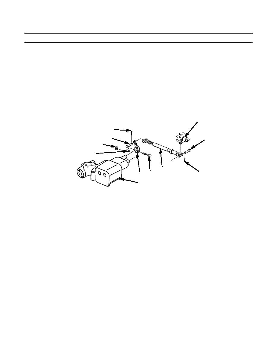
STEERING CLUTCH LEVERS AND LINKAGE MAINTENANCE - CONTINUED
0123 00
DISASSEMBLY- CONTINUED
3.
Remove cotter pin (22) and pin (23) from end of rod (24) at bellcrank (21). Discard cotter pin.
4.
Remove cotter pin (25) and pin (26) from end of rod (24) at control valve lever (27). Remove rod. Discard cotter pin.
5.
Remove nut (28), capscrew (29), control valve lever (27) and key (30) from control valve (31). Discard key.
ASSEMBLY
1.
Install control valve lever (27) on control valve (31) with new key (30) and capscrew (29) and nut (28).
2.
Connect one end of rod (24) to lever (27) with pin (26) and new cotter pin (25).
3.
Connect other end of rod (24) to bellcrank (21) with pin (23) and new cotter pin (22).
21
25
26
23
28
30
24
22
29
27
31
386-735
4.
Connect bottom end of rod (18) to bellcrank (21) with pin (20) and new cotter pin (19).
5.
Connect top end of rod (18) to lever (11) with pin (17) and new cotter pin (16).
6.
Position bar (13) inside dash assembly.
7.
Install nut (12) loosely on rod (15) and insert rod into bar (13).
8.
Install handle (14) on rod (15).
9.
Position levers (8 and 11) on bar (13).
10.
Install pin (10) and new cotter pin (9) to secure lever (11) to bar (13).
11.
Install pin (6) and new cotter pin (7) to secure lever (8) to bar (13).
12.
Tighten nut (12) against rod (15).
0123 00-3
|
|
Privacy Statement - Press Release - Copyright Information. - Contact Us |
