 |
|||
|
|
|||
|
|
|||
| ||||||||||
|
|
 TM 5-2410-233-23
STEERING CLUTCH LEVERS AND LINKAGE ADJUSTMENT - CONTINUED
0122 00
ADJUSTMENT - CONTINUED
2.
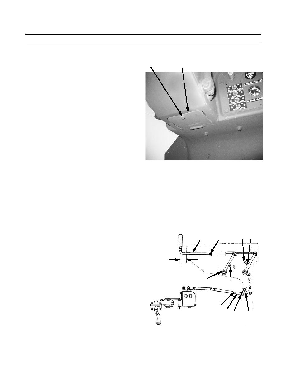
Remove capscrew (6), lockwasher (7) and washer (8)
6,7,8
and open access cover (9) on underside of governor
9
control console. Discard lockwasher.
386-767
3.
Loosen self-locking nut (10), remove cotter pin (11) and pin (12), and disconnect rod end (13) from bellcrank (14). Dis-
card cotter pin.
4.
Push lever (15) to clutch engaged position, all the way toward front of machine against bumper (16).
5.
Adjust rod end (13) so pin holes in rod end are aligned with holes in bellcrank (14).
6.
Turn rod end (13) an additional 1/2 turn to shorten overall length of control rod.
7.
Tighten self-locking nut (10) and install pin (12) and new cotter pin (11) to connect rod end (13) to bellcrank (14).
8.
Loosen self-locking nut (17) and, with lever (15) for-
ward in the clutch engaged position, adjust steering
20 19
17
18
clutch control lever (18) so distance (A) between cen-
ter line of lever and face of dash is 2.50 in. (6.35 cm).
9.
Tighten self-locking nut (17).
10.
Loosen nut (19) on stop bolt (20). Turn stop bolt into
A
lever to provide clearance between bolt head and stop
plate.
15
11.
Pull steering clutch control lever (18) back slowly
16
until a definite resistance is felt. Turn stop bolt (20)
out until head of stop bolt contacts stop plate. Turn
stop bolt out an additional 1/2 turn (to lengthen).
10
13 11,12
12.
Tighten nut (19).
14
13.
Close access cover (9) at governor control console and
secure with washer (8), new lockwasher (7) and cap-
386-736
screw (6).
0122 00-2
|
|
Privacy Statement - Press Release - Copyright Information. - Contact Us |