 |
|||
|
|
|||
|
|
|||
| ||||||||||
|
|
 TM 5-2410-233-23
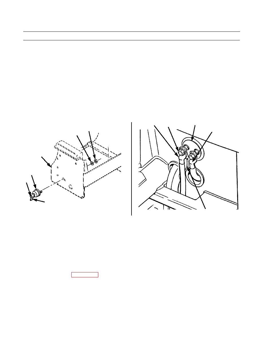
BATTERY DISCONNECT SWITCH REPLACEMENT - CONTINUED
0076 00
REMOVAL - CONTINUED
NOTE
Tag cables to ensure correct installation.
3.
Remove two nuts (3) and lockwashers (4). Discard lockwashers.
4.
Remove cables (5 and 6) and wire (7).
5.
Remove nut (8) and lockwasher (9) from switch mounting stud. Discard lockwasher.
6.
Remove switch assembly (10) from seat base (11).
10
6
3,4
5
8
9
11
10
1
2
386-443
7
386-445
INSTALLATION
1.
Position switch assembly (10) onto seat base (11).
2.
Install new lockwasher (9) and nut (8) to switch mounting stud.
3.
Install wire (7) and cables (5 and 6) with two new lockwashers (4) and nuts (3).
4.
Return seat to normal position (TM 5-2410-233-10).
5.
Install switch knob (2) and screw (1).
6.
Connect battery cables (WP 0080 00).
7.
Turn battery disconnect switch to ON position (TM 5-2410-233-10).
8.
Check operation of switch.
END OF WORK PACKAGE
0076 00-2
|
|
Privacy Statement - Press Release - Copyright Information. - Contact Us |
