 |
|||
|
|
|||
|
|
|||
| ||||||||||
|
|
 TM 5-2410-233-23
GOVERNOR CONTROLS AND LINKAGE MAINTENANCE - CONTINUED
0054 00
INSTALLATION - CONTINUED
16.
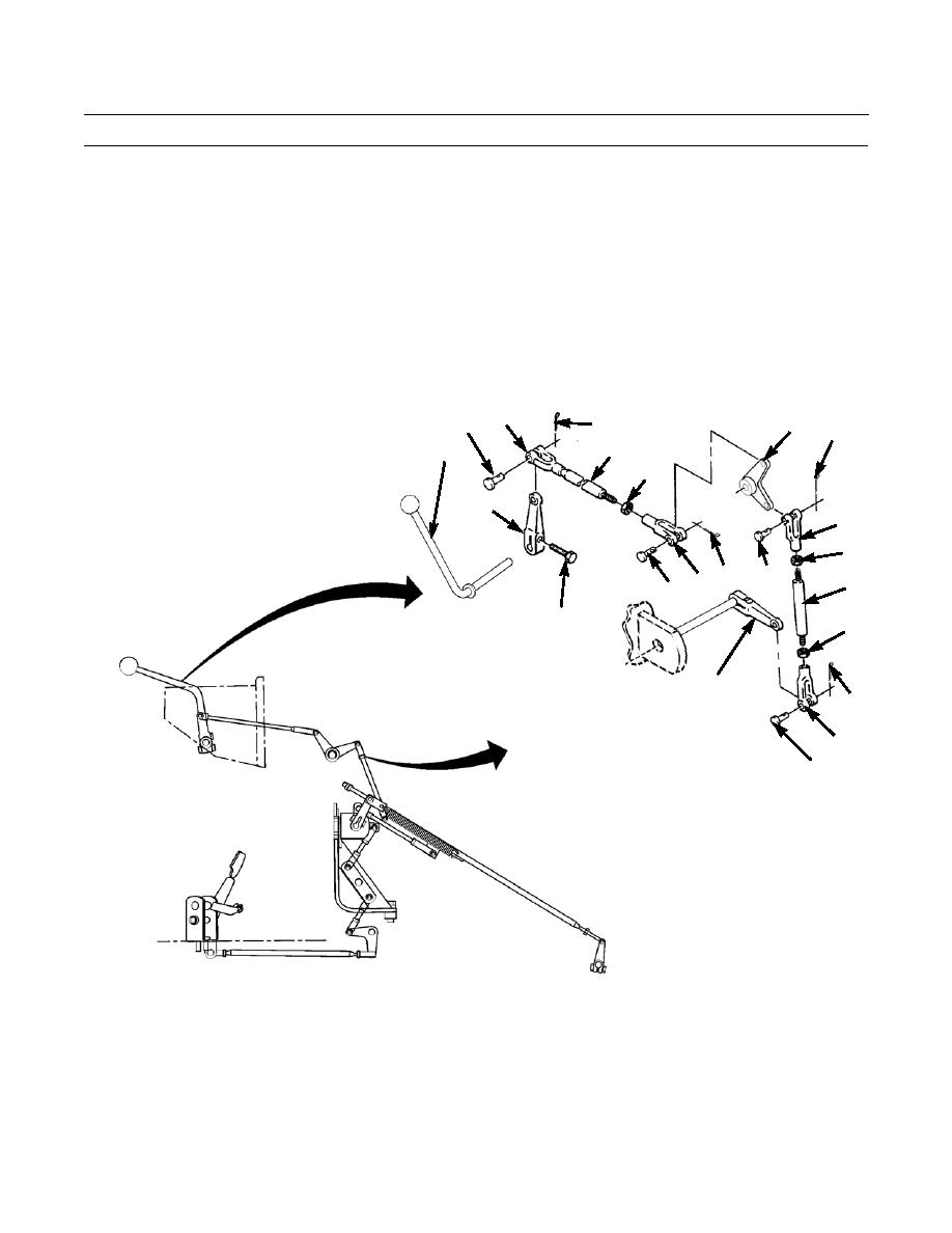
Install throttle lever (27) through lever (11) and secure with capscrew (26) in back of dash assembly.
17.
Install jam nuts (16 and 17) to rod (21).
18.
Connect lower end of rod (21) to clevis (24). Install clevis on lever (25) with pin (23) and new cotter pin (22).
19.
Connect upper end of rod (21) to clevis (20). Install clevis on bell crank (15) with pin (19) and new cotter pin (18).
Adjust IAW Adjustment at the end of this work package.
20.
Install clevis (14) on bellcrank (15) with pin (13) and new cotter pin (12).
21.
Install clevis (9) on lever (11) with pin (8) and new cotter pin (7). Adjust IAW Adjustment at the end of this work
package.
9
8
15
7
18
10
27
6
11
20
16
14 12
19
21
13
26
17
25
22
24
23
386-758
0054 00-9
|
|
Privacy Statement - Press Release - Copyright Information. - Contact Us |