 |
|||
|
|
|||
|
|
|||
| ||||||||||
|
|
 TM 5-2410-233-23
GOVERNOR CONTROLS AND LINKAGE MAINTENANCE - CONTINUED
0054 00
REMOVAL - CONTINUED
NOTE
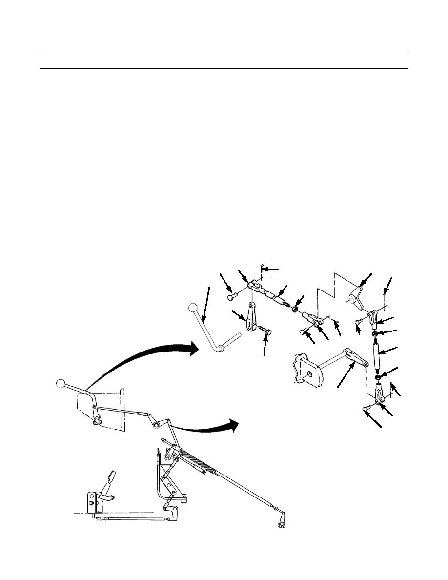
Components shown are typical. There may be variations on your machine.
2.
Loosen jam nut (6) and remove cotter pin (7) and pin (8) from clevis (9). Remove upper end of rod (10) from lever (11).
Discard cotter pin.
3.
Remove cotter pin (12) and pin (13) from clevis (14). Remove lower end of rod (10) from bell crank (15). Discard cotter
pin.
4.
Remove rod assembly (10).
5.
Loosen jam nuts (16 and 17) and remove cotter pin (18), pin (19) from clevis (20). Remove upper end of rod (21) from
bell crank (15). Discard cotter pin.
6.
Remove cotter pin (22) and pin (23) from clevis (24) and remove lower end of rod (21) from lever (25). Discard cotter
pin.
7.
Remove rod assembly (21).
NOTE
If lever or component inside of a lever requires removal, drive small chisel into slot in lever to open it up for
removal.
8.
Remove capscrew (26) from lever (11) and remove throttle lever (27) from back of dash assembly.
9
8
15
7
18
10
27
6
11
20
16
14 12
19
21
13
26
17
25
22
24
23
386-758
0054 00-2
|
|
Privacy Statement - Press Release - Copyright Information. - Contact Us |
