 |
|||
|
|
|||
|
Page Title:
ADJUST TIMING BY TIMING PIN METHOD - CONTINUED |
|
||
| ||||||||||
|
|
 TM 5-2410-233-23
FUEL INJECTION PUMP AND GOVERNOR TIMING AND ADJUSTMENT - CONTINUED
0053 00
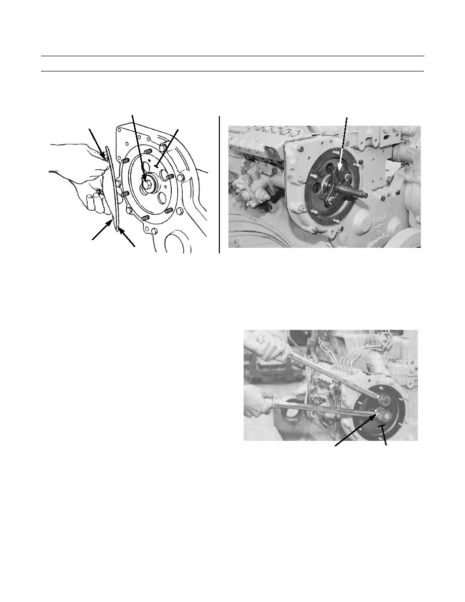
ADJUST TIMING BY TIMING PIN METHOD - CONTINUED
(3)
Install gear puller, as shown, and loosen drive gear (10) from fuel pump camshaft.
9
GEAR PULLER
5,6
10
7
8
386-781
386-271
(4)
Rotate engine 60 degrees to the right to put no. 1 piston at top dead center.
(5)
Tighten capscrew (9) finger-tight. Ensure timing pin (4) is in groove of fuel pump camshaft.
(6)
Slowly rotate engine to the left until timing bolt can be installed in flywheel.
(7)
Install torque wrench adapter on drive gear (10). Use two 3/8 in.-24NF bolts, 1 in. (25.4 mm) long, to
secure adapter to puller holes in gear.
(8)
Hold torque of 45-50 lb-ft (61-68 Nm)
on torque wrench adapter in a rotation to
the right, and tighten capscrew (9) to 200
lb-ft (271 Nm).
386-785
10
9 (HIDDEN)
(9)
Remove timing bolt from flywheel. Remove timing pin (4) from fuel pump camshaft.
(10)
Rotate engine two revolutions to the left. If timing bolt can be installed in flywheel and timing pin (4) can
be installed in fuel pump camshaft, timing is correct. Return to step 8.
(11)
If either timing pin or timing bolt cannot be installed, repeat steps 1-10.
8.
Remove 3/8 in.-16NC bolt from timing hole in flywheel housing and install plug.
9.
Remove timing pin. Install new gasket (3) and timing cover (2) to side of fuel injection pump housing with four bolts
(1).
0053 00-3
|
|
Privacy Statement - Press Release - Copyright Information. - Contact Us |
