 |
|||
|
|
|||
|
|
|||
| ||||||||||
|
|
 TM 5-2410-233-23
REAR ACCESSORY DRIVE GEARS REPLACEMENT - CONTINUED
0035 00
REMOVAL - CONTINUED
2.
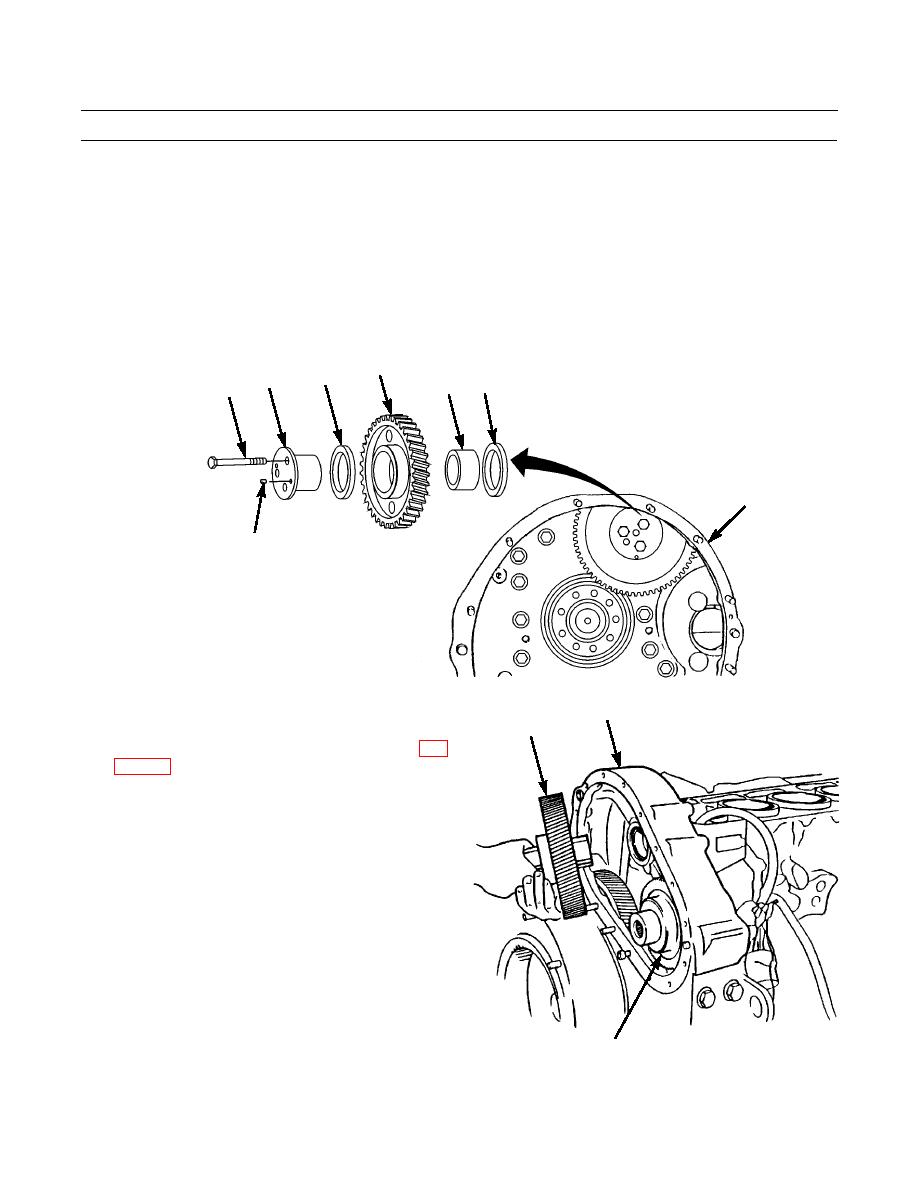
If idler gear (4) is to be removed, perform the following steps:
a.
Remove three capscrews (5), dowel (6), shaft (7), washer (8) and idler gear (4) from flywheel housing (3).
b.
If necessary, use a bearing puller to remove bearing (9) and washer (10) from flywheel housing (3).
INSTALLATION
1.
To install idler gear (4), perform the following steps:
a.
Use driver to install bearing (9) and washer (10) into flywheel housing (3).
b.
Place idler gear (4), washer (8), shaft (7) and dowel (6) into position. Install three capscrews (5) that secure shaft
assembly to flywheel housing (3).
4
8
7
10
9
5
3
6
386-192
2.
Install drive gear (2) and then drive gear (1) into fly-
3
1
wheel housing (3).
3.
Install rear accessory drive gear cover assembly (WP
4.
Run engine and check for proper operation (TM 5-
2410-233-10).
386-203
2
END OF WORK PACKAGE
0035 00-2
|
|
Privacy Statement - Press Release - Copyright Information. - Contact Us |