 |
|||
|
|
|||
|
|
|||
| ||||||||||
|
|
 TM 5-2410-233-23
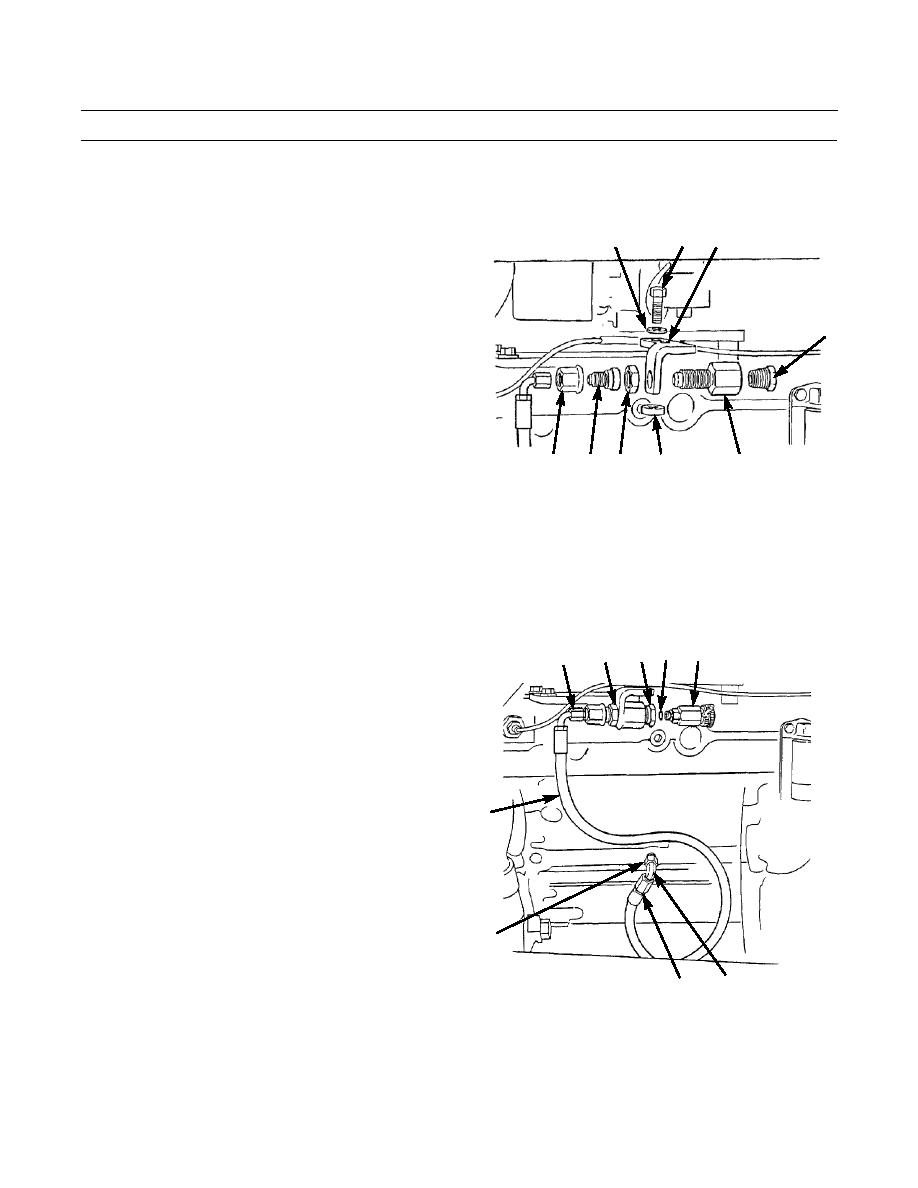
ENGINE OIL SAMPLING VALVE AND HOSE REPLACEMENT - CONTINUED
0013 00
REMOVAL - CONTINUED
5.
Remove nut (10) from connector (11) and remove nut and reducer (7).
6.
Remove adapter (2) from connector (11).
15
14
16
7.
Remove nut (13) from connector (11) and remove
connector from bracket (14).
8.
Remove capscrew (15), washer (16) and spacer (17)
from bracket (14) and remove bracket from cylinder
2
head.
11
386-103
13
17
10
7
INSTALLATION
1.
Place spacer (17) and bracket (14) in position on cylinder head and install washer (16) and capscrew (15).
2.
Place connector (11) in position on bracket (14). Install nut (13) to secure connector.
3.
Install adapter (2) onto connector (11).
4.
Place reducer (7) through nut (10) and install nut onto
3
1
2
7
6
connector (11).
5.
Install adapter (9) in engine block, if removed, and
secure elbow (5) onto adapter.
6.
Place hose (8) into position and install hose nut (4)
onto elbow (5). Install hose nut (6) onto end of reducer
(7).
7.
Lightly coat with oil and install new O-ring (3) onto
valve (1).
8
8.
Install valve (1) into adapter (2) and tighten valve to
180 lb-in. (20 Nm).
9.
Run engine and check for leaks (TM 5-2410-233-10).
9
386-080
5
4
END OF WORK PACKAGE
0013 00-2
|
|
Privacy Statement - Press Release - Copyright Information. - Contact Us |
