 |
|||
|
|
|||
|
Page Title:
STEERING AND BRAKE SYSTEM |
|
||
| ||||||||||
|
|
 TM 5-2410-233-10
THEORY OF OPERATION - CONTINUED
0003 00
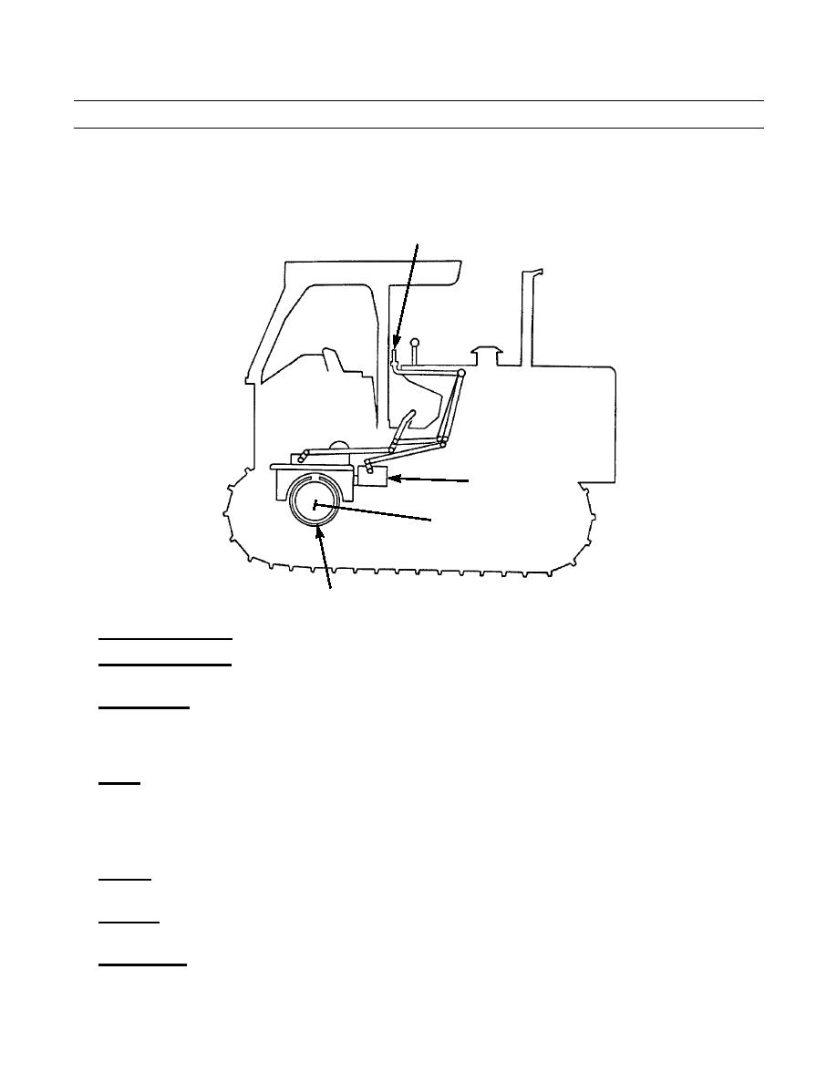
STEERING AND BRAKE SYSTEM
STEERING
CLUTCH LEVERS
STEERING
CONTROL VALVE
STEERING
CLUTCH
386-471
BRAKE
1.
Steering Clutch Levers. Levers serve as mechanical linkage to the steering control valve.
2.
Steering Control Valve. The valve is connected mechanically to the steering clutch levers. The valve directs the flow of
pressurized oil in response to the movement of the levers.
3.
Steering Clutch. There is one steering clutch for each track. They control the steering of the tractor. Mechanically oper-
ated, each steering clutch is controlled by the steering clutch lever in the operator's station. When turning left, the left
clutch is released which causes the left track to stop moving and act as a pivot for the tractor to turn on. The same thing
happens when turning right.
4.
Brakes. The tractor has two band-type brakes (one on each steering clutch drum) which are used to stop the movement of
the tractor and to assist with the steering of the tractor. When the steering clutch levers are pulled completely out or the
brake pedals are depressed, the bands tighten around the steering clutch drums.
ELECTRICAL SYSTEM
1.
Batteries. The batteries provide power for three circuits; the charging circuit, the starting circuit and the lighting (low
amperage) circuit. Two 12-volt batteries are connected in series to provide 24-volt, 1200 CCA starting power.
2.
Alternator. The 24-volt, 50-amp alternator, an integral part of the charging circuit, provides current when the engine is
running.
3.
Starting Motor. Part of the starting circuit, the starting motor is used to turn the engine flywheel in order to start the
engine.
0003 00-5
|
|
Privacy Statement - Press Release - Copyright Information. - Contact Us |