 |
|||
|
|
|||
|
Page Title:
LOCATION AND DESCRIPTION OF MAJOR COMPONENTS |
|
||
| ||||||||||
|
|
 TM 5-2410-233-10
EQUIPMENT DESCRIPTION AND DATA - CONTINUED
0002 00
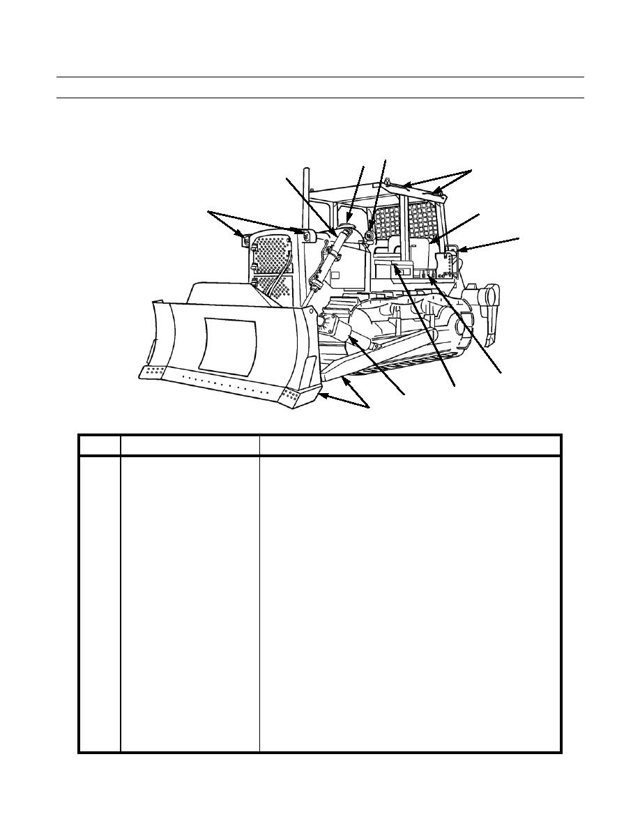
LOCATION AND DESCRIPTION OF MAJOR COMPONENTS
4
3
5
2
1
6
5
7
8
9
10
386-001
KEY
COMPONENT
DESCRIPTION
1
Front Flood Lights
Illuminate work area to front of machine.
2
Lift Cylinders
Raise or lower bulldozer blade. Located on both sides of machine.
3
Engine Air Precleaner
Prevents debris from entering engine air intake system.
4
Center Flood Lights
Illuminate track and rear of blade.
5
Grabhandles
Provide a handhold for personnel climbing on machine.
6
Fuel Tank
Stores fuel supply for engine operation.
7
Toolbox
Provides stowage for tools or other items required by operator.
8
Battery Box
Enclosure protects batteries from damage. Two batteries inside are
easily accessible for servicing.
9
Tilt Cylinder
Used in conjunction with brace (on right side) to adjust angle of
bulldozer blade.
10
SU Blade Assembly
Used for earthmoving operations or as a push block. Consists of
moldboard, removable cutting edges and end bits, and blade pusharms
that connect blade to the tractor. Reinforced plate in center of blade is
used to push-assist scrapers. Back-rip scarifiers are attached to the
back of the blade and can be lowered and locked in place with pins for
scarifying. Blade assembly controls are operated from operator seat.
0002 00-4
|
|
Privacy Statement - Press Release - Copyright Information. - Contact Us |
