 |
|||
|
|
|||
|
|
|||
| ||||||||||
|
|
 TM 9-2320-364-34-1
1-12. ELECTRICAL SYSTEM (CONT).
STEERING WHEEL
SHOWN REMOVED
FOR CLARITY
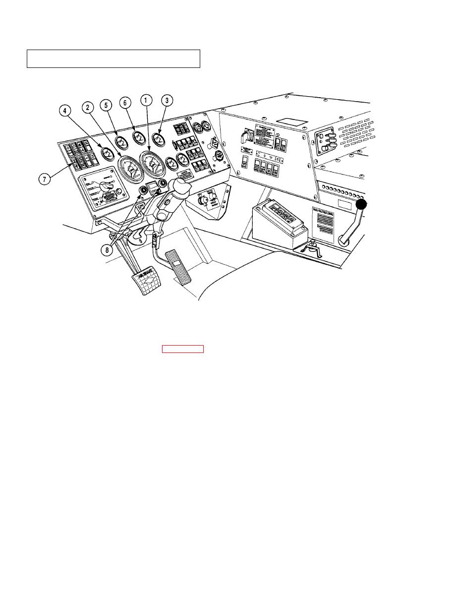
f. Instruments. The instrument system (Figure 1-15) includes all gages that give the operator information. The
speedometer (1) receives signals from a sending unit mounted on the transfer case. Tachometer (2) input is provided
from the DDEC controller. The fuel gage (3), oil pressure gage (4), water temperature gage (5) and transmission oil
temperature gage (6) all receive electrical signals from sending units. These sending units monitor fluid level,
pressure and temperature and send this information to the gages.
g. Warning Lights and Buzzers. The warning lights (7) and buzzers (8) in the cab are activated by
sensors located in different systems. These include low air pressure, low engine oil pressure, low hydraulic oil
level and high water temperature. When one or more of these sensors are activated, they energize the proper
light and/or buzzer, informing the operator of a problem.
1-18
|
|
Privacy Statement - Press Release - Copyright Information. - Contact Us |
