 |
|||
|
|
|||
|
|
|||
| ||||||||||
|
|
 TM 9-2320-364-20-1
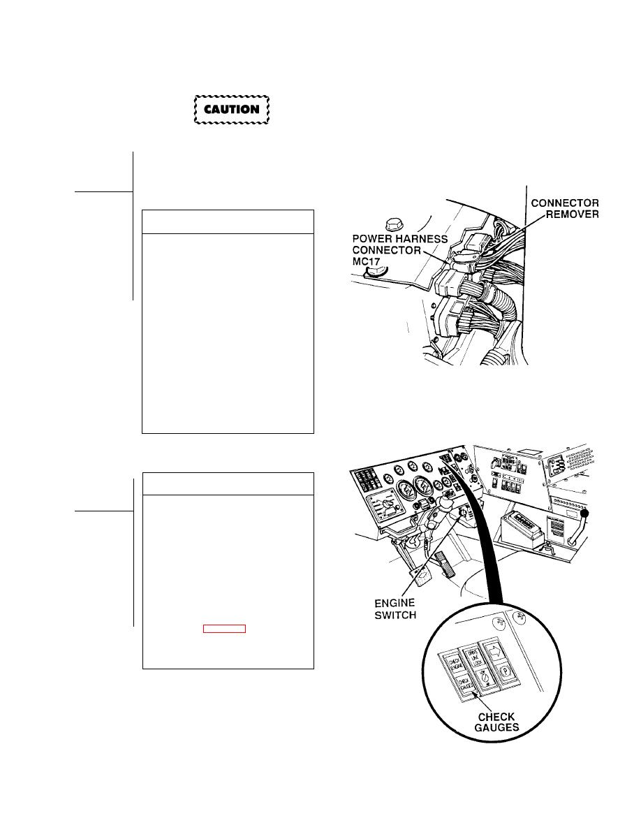
DDEC ECM connectors terminals are easily
damaged. Use care when connecting and
disconnecting connectors.
VISUAL INSPECTION
(1) Disconnect all connectors at
DDEC ECM (Para 7-56).
(2) Check all terminals at harness
connectors (ECM and harness side)
for damage; bent, corroded and
unseated pins or terminals.
(a) If harness connector(s) is
damaged, repair connector(s)
(Para 7-101) and perform Steps (3)
through (5) below.
(b) If DDEC ECM connector is
damaged, replace ECM
(Para 7-56).
(c) If harness connector and DDEC
ECM harness connectors are OK,
replace DDEC ECM (Para 7-56).
(3) Connect engine harness connector to
DDEC ECM and tighten screw.
(4) Install heat shield and two screws.
(5) Close top engine access cover.
VERIFY REPAIR
(1) Turn ON ENGINE switch
(TM 9-2320-364-10).
(2) Clear codes on DDR (Para 2-24).
(3) If CGL does not stay ON, start engine
and run for 8 minutes or until CGL
comes ON.
(a) If check engine light comes on for
about five seconds and then goes
off, fault has been corrected.
Perform Steps (4) and (5) below.
(b) If check engine light comes on
and stays on, perform Steps (4)
and (5) below and go to Fault
Index (Table 2-16).
(4) Turn OFF ENGINE switch.
(5) Disconnect DDR from DDL
connector MC13.
2-511/(2-512 blank)
|
|
Privacy Statement - Press Release - Copyright Information. - Contact Us |
