 |
|||
|
|
|||
|
|
|||
| ||||||||||
|
|
 TM 9-2320-364-20-1
Remove all jewelry such as rings, dog tags, bracelets, etc. If jewelry or tools contact positive electrical
circuits, a direct short may result. Damage to equipment, injury or death to personnel may occur.
Allow engine to cool before performing
troubleshooting maintenance. If necessary
use insulated pads and gloves. Hot engine
components will burn and cause personnel
injury.
Use jumperwire only between terminals
indicated. Failure to comply may result in
damage to DDEC components or wiring.
DDEC ECM connector terminals are easily
damaged. Use care when connecting and
disconnecting connectors.
NOTE
The following steps should only be
used if troubleshooting was started
at DDEC II Troubleshooting (All Conditions)
and you were referred here.
VISUAL INSPECTION
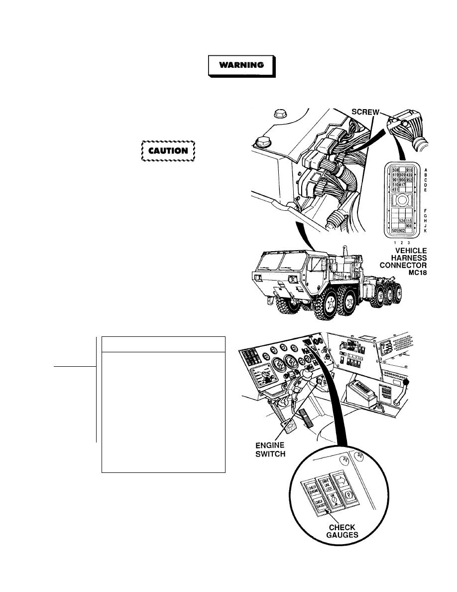
(1) Loosen screw and disconnect vehicle
harness connector MC18 at
DDEC ECM.
(2) Place jumperwire between terminal B2
at vehicle harness connector MC18
and a known good ground.
(3) Turn ON ENGINE switch
(TM 9-2320-364-10).
(4) Is CGL OFF with jumperwire installed
at vehicle harness connector MC18?
(a) If CGL is ON, remove jumperwire,
turn OFF ENGINE switch and go
to Step 4 of this fault.
(b) If CGL is OFF, remove
jumperwire, turn OFF ENGINE
switch and go to Step 2 of this
Fault.
|
|
Privacy Statement - Press Release - Copyright Information. - Contact Us |
