 |
|||
|
|
|||
|
|
|||
| ||||||||||
|
|
 TM 9-2320-364-20-1
Allow engine to cool before performing troubleshooting maintenance. If necessary use insulated pads
and gloves. Hot engine components will burn and cause injury to personnel.
Remove all jewelry such as rings, dog tags, bracelets, etc. If jewelry or tools contact positive electrical
circuits, a direct short may result. Damage to equipment, injury or death to personnel may occur.
VOLTAGE TEST
(1) Set multimeter select switch to
volts dc.
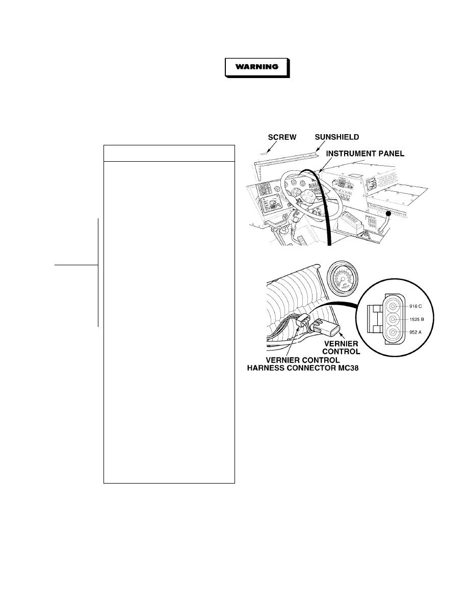
(2) Connect positive (+) multimeter lead
to vernier control harness connector
MC38, terminal C.
(3) Connect negative (- ) multimeter
-
lead to a known good ground.
(4) Turn ON ENGINE switch
(TM 9-2320-364-10).
(5) Are there 4.7 to 5.2 vdc present at
wire 916 at vernier control harness
connector MC38, terminal C and a
known good ground.
(a) If there are 4.7 to 5.2 vdc present,
repair wire 916 (see schematic
Fig 2-1) or notify DS
Maintenance and perform Steps
(9) through (11) below.
(b) If there are less than or more than
4.7 to 5.2 vdc present, perform
Step (6) below.
(6) Connect positive (+) multimeter lead
to vernier control harness connector
MC38, terminal A.
(7) Connect negative (- ) multimeter
-
lead to a known good ground.
(8) Are there 4.7 to 5.2 vdc present at
wire 952 at vernier control harness
connector MC38, terminal A and a
known good ground.
(a) If there are less than 4.7 vdc
present, turn OFF ENGINE
switch and repair wires 916
and/or 952 (see schematic
Fig 2-1) or notify DS
Maintenance and perform
Steps (9) through (11) below.
(b) If there are 5.2 vdc or more
present, perform Steps (9) and
(11) below and go to Step 6 of
this Fault.
(9) Turn OFF ENGINE switch.
(10) Connect vernier control harness
connector MC38.
(11) Install instrument panel and
sunshield with ten screws.
|
|
Privacy Statement - Press Release - Copyright Information. - Contact Us |
