 |
|||
|
|
|||
|
|
|||
| ||||||||||
|
|
 TM 9-2320-364-20-1
Remove all jewelry such as rings, dog tags, bracelets, etc. If jewelry or tools contact positive electrical
circuits, a direct short may result. Damage to equipment, injury or death to personnel may occur.
Use jumperwire only between terminals
indicated. Failure to comply may result in
damage to DDEC components or wiring.
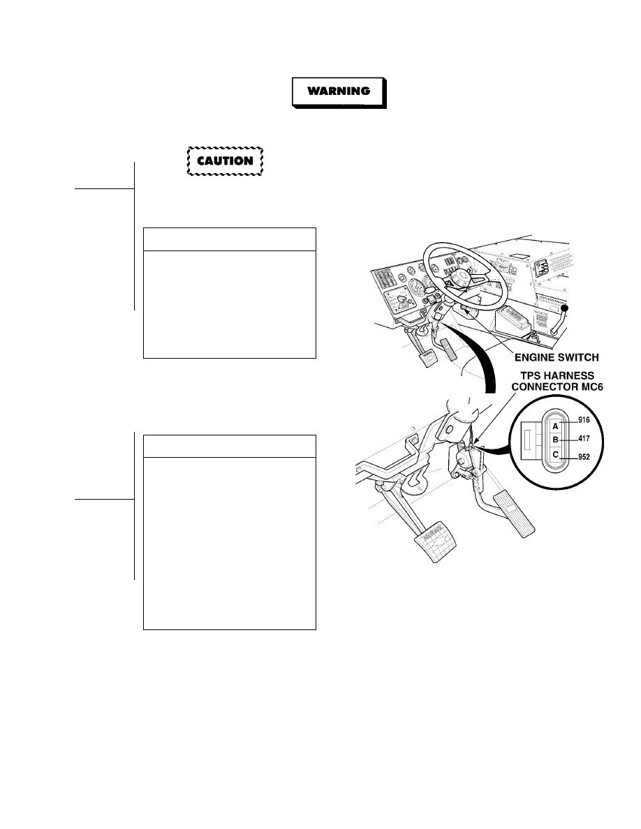
VISUAL INSPECTION
(1) Disconnect TPS harness connector
from TPS.
(2) Inspect TPS connectors (sensor side
and harness side) for damage; bent,
corroded and unseated pins or
terminals.
(a) If connectors are damaged, repair
connectors (Para 7-101).
(b) If connectors are free of damage,
replace TPS (Para 7-58).
VOLTAGE TEST
(1) Remove jumperwire.
(2) Set multimeter select switch to
volts dc.
(3) Connect positive (+) multimeter lead
to wire 952 on TPS harness
connector, terminal C.
(4) Connect negative (- ) multimeter lead
-
to wire 916 at TPS harness connector,
terminal A.
(5) Turn ON ENGINE switch
(TM 9-2320-364-10).
(a) If less than 4 vdc are present, turn
OFF ENGINE switch and go to
Step 9 of this Fault.
(b) If 4 to 6 vdc are present, turn
OFF ENGINE switch and go to
Step 6 of this Fault.
|
|
Privacy Statement - Press Release - Copyright Information. - Contact Us |
