 |
|||
|
|
|||
|
|
|||
| ||||||||||
|
|
 TM 9-2320-364-20-1
Remove all jewelry such as rings, dog tags, bracelets, etc. If jewelry or tools contact positive electrical
circuits, a direct short may result. Damage to equipment, injury or death to personnel may occur.
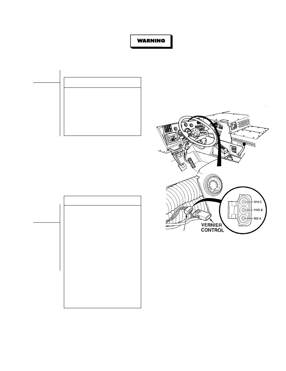
VISUAL INSPECTION
Check terminals at vernier control harness
connectors (connector and harness side) for
damage; bent, corroded and unseated pins
or terminals.
(1) If harness connectors are
damaged, repair connectors
(Para 7-101).
(2) If harness connectors are OK,
replace vernier control
(Para 7-100).
VOLTAGE TEST
(1) Set multimeter select switch to
volts dc.
(2) Connect positive (+) multimeter lead
to vernier control harness connector
MC38, terminal A.
(3) Connect negative (- ) multimeter lead
-
VERNIER CONTROL
to vernier control harness connector
HARNESS CONNECTOR MC38
MC38, terminal B.
(4) Turn ON ENGINE switch
(TM 9-2320-364-10).
(5) Turn on crane power switch and
latch high idle.
(a) If there is 1.0 vdc or more
present, turn OFF ENGINE
switch and repair wires 916,
1525 and/or 510 (see
schematic Fig 2-1) or
notify DS Maintenance.
(b) If less than 1.0 vdc is present,
wires 916, 1525 and 510
are OK.
(6) Turn OFF ENGINE switch and crane
power switch.
2-197
|
|
Privacy Statement - Press Release - Copyright Information. - Contact Us |
