 |
|||
|
|
|||
|
|
|||
| ||||||||||
|
|
 TM 9-2320-360-34-2
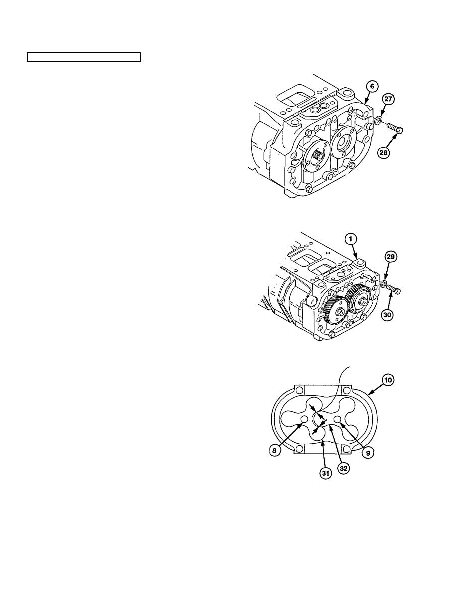
20-2. BLOWER REPAIR (CONT)
(33) Install four washers (27) and four 5/16 x 2 in.
screws (28) in front end plate (6). Torque to 180
lb-in. (20.3 Nm).
(34) Install four washers (29) and four 5/16 x 2-1/4 in.
screws (30) in rear end plate (1). Torque to 180
lb-in. (20.3 Nm).
(35) Position blower (10) on side.
NOTE
Shop cloth must be removed
before timing rotors and setting
clearances.
Clearance between rotor lobes
should be 0.013 in. (3.3 mm).
Clearance
is
adjusted
by
installing shims between gears
and bearings to move timing
gears in or out.
Minimum clearances are listed for
feeler gage measurements.
Six checks must be made on both
air inlet and air outlet sides to
determine clearance between
rotors.
Checks are made 1 in. (25.4 mm)
from end of blower. Both ends
must be checked.
(36) Place 0.013 in. (3.3 mm) feeler gage between
rotor lobes (31 and 32).
CAUTION
Do not force feeler gage between
rotors. Failure to comply may result
in damage to equipment.
NOTE
If feeler gage cannot be inserted
between rotors, go to step (40).
(37) Rotate rotors (8 and 9) to position feeler gage
between rotor lobes (31 and 32).
(38) Remove feeler gage from between rotor lobes
(31 and 32).
(39) Repeat steps (36) thru (38) until checks have
been made on each lobe of rotors (8 and 9) from
both inlet and outlet sides of blower (10).
20-12
|
|
Privacy Statement - Press Release - Copyright Information. - Contact Us |
