 |
|||
|
|
|||
|
|
|||
| ||||||||||
|
|
 TM 9-2320-360-34-2
CAUTION
Water nozzles must be installed so
holes are pointed toward cylinder.
Failure to comply may result in
Improper coolant flow and engine
overheating.
NOTE
Do step (29) if water nozzles were
removed.
Ensure water nozzle fits tightly.
Water nozzles must be flush
or recessed less than 0.015
in.
(0.38 mm) below
cylinder head surface.
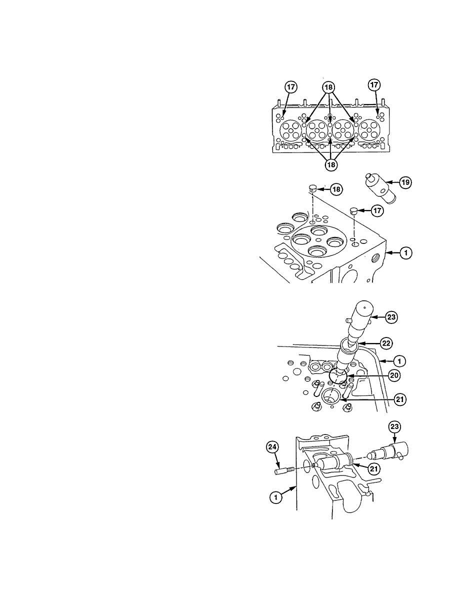
End two water nozzles have one
hole. Six water nozzles between
cylinders have two holes.
(29) Install water nozzle (17 or 18) into cylinder head
(1) with nozzle holes facing in direction of arrows
using water nozzle installer (19).
NOTE
Do steps (30) thru (49) if injector
tubes were removed.
(30) Install new preformed packing
(20)
In
counterbore (21) of cylinder head (1).
(31) Install injector tube (22) in injector bore of
cylinder head (1) using injector tube installer
(23).
(32) Install pilot (24) in bottom of injector tube
installer (23).
NOTE
Tube flange at seal ring end may
protrude 0.120 in. (3.048 mm) above
cylinder head casting. Seal is formed
when O-ring is pressed between head
counterbore and outside diameter of
injector tube. Tube flange is used to
retain seal ring in head counterbore.
(33) Drive injector tube (22) into bore (21) of cylinder
head (1).
19-51
|
|
Privacy Statement - Press Release - Copyright Information. - Contact Us |
