|
| |
TM 9-2320-356-BD
6.
Connect an insulator to each end of the wire used for the antenna.
7.
Tie an insulator to the middle of the antenna wire to be used for elevating the
antenna.
8.
Connect tiedown wires to the outside of the insulators at the ends of the
antenna wire.
9.
Connect the counterpoise to the insulators at the same point as the tiedown
wires.
10. Connect a long rope or wire to the outside of the insulator at the middle of
the antenna wire.
11. Raise the center of the antenna up the support approximately 30 feet.
12. Stretch the antenna and counterpoise ends out in a straight line between you
and in line with the vehicle and the desired station.
13. Drive stakes in the ground by each tiedown wire.
14. Stretch the antenna and counterpoise tight and tie to the stakes.
15. Connect a wire from the antenna to the center of the antenna connection on the
radio.
16. Route a second wire, for ground, from any convenient screw on the radio case
and connect it to the counterpoise wire.
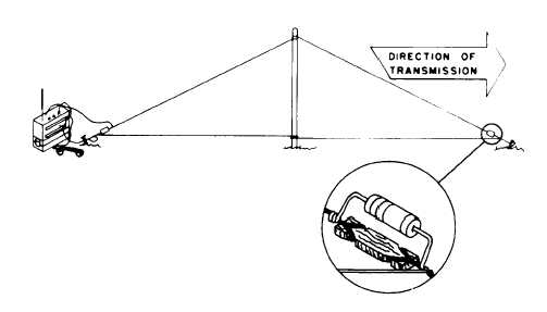
17. Connect a 600-ohm carbon resistor across the insulator on the transmission end
of the antenna.
Refer to paragraph 15-7 for construction of a 600-ohm resistor.
18. Record BDAR action taken.
When the mission is complete, as soon as
practicable, repair using standard maintenance procedures.
15-13
|