 |
|||
|
|
|||
|
Page Title:
Illustration 147 Schematic Drawing |
|
||
| ||||||||||
|
|
 60
TM 9-2320-312-24-2
Truck Engine
Disassembly and Assembly Section
g00759921
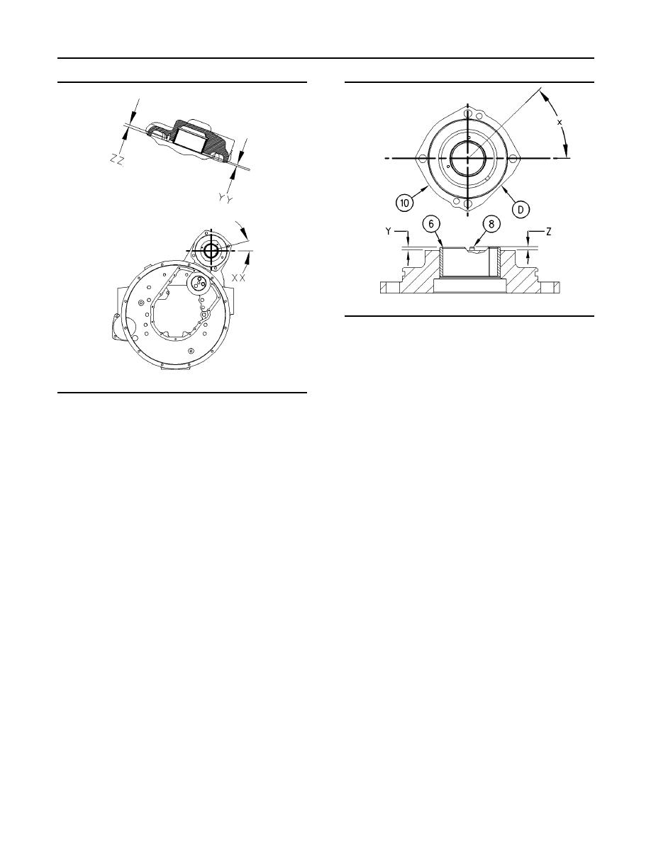
Illustration 148
(D) The flat side of Adapter Assembly (10)
(X) location of bearing joint
(Y) height of bearing
(Z) height of dowel
4. Place adapter assembly (10) on the work surface.
g00759999
The outside face should be down. Install bearing
Illustration 147
(6) in adapter assembly (10) with Tooling (B).
(XX) location of bearing joint
(YY) height of bearing
(ZZ) height of dowel
Note: The split in the bearing should be located
at Angle (X), which is 45 10 degrees from
1. Use Tooling (B) to install bearing (3) in the
the centerline in the adapter assembly (10). The
housing for the Rear Power Take-Off (26).
bearing should extend beyond the surface of the
adapter assembly (10) by a Distance (Y) which is
Note: The bearing joint is located at an Angle (XX)
3.1 0.5 mm (0.12 0.02 inch).
that is 15 3 degrees from the horizontal centerline.
The oil hole in the bearing must align with the oil
5. Install dowels (8) and thrust washer (7) in
gallery in the housing for the RPTO. The bearing
adapter assembly (10). Refer to Illustration 146.
should extend beyond the surface of the housing
for the RPTO by a Distance (YY) of 3.1 .5 mm
Note: The dowels should extend beyond the surface
(0.12 0.02 inch).
of the adapter assembly (10) by a distance of
3.5 0.2 mm (0.14 0.01 inch).
2. Install dowels (1) in the RPTO housing (26).
6. Install O-ring seal (9) on adapter assembly (10).
Note: The dowels should extend beyond the surface
of the RPTO housing by a distance 3.5 .2 mm
7. Turn over adapter assembly (10). Use Tooling (C)
(0.14 0.01 inch).
to install lip type seal (11). Lubricate lip type seal
(11) lightly with the lubricant that is being sealed.
3. Install thrust washer (2) into RPTO housing (26).
Note: Lip seal (11) should be installed to a depth of
2.5 0.5 mm (0.1 0.02 inch).
|
|
Privacy Statement - Press Release - Copyright Information. - Contact Us |
