 |
|||
|
|
|||
|
|
|||
| ||||||||||
|
|
 TM 9-2320-312-24-2
Truck Engine
Disassembly and Assembly Section
1. Heat the flywheel ring gear to a maximum
2. Install Tooling (A) on the flywheel. Fasten a
temperature of 204 C (400 F). Do not use a
suitable lifting device to the flywheel.
torch to heat the flywheel ring gear. Install the
flywheel ring gear on the flywheel. Position the
flywheel ring gear with the part number toward
the crankshaft. Allow the flywheel ring gear to
cool. Use a soft hammer in order to seat the
flywheel ring gear against the shoulder of the
flywheel.
g00613482
Illustration 127
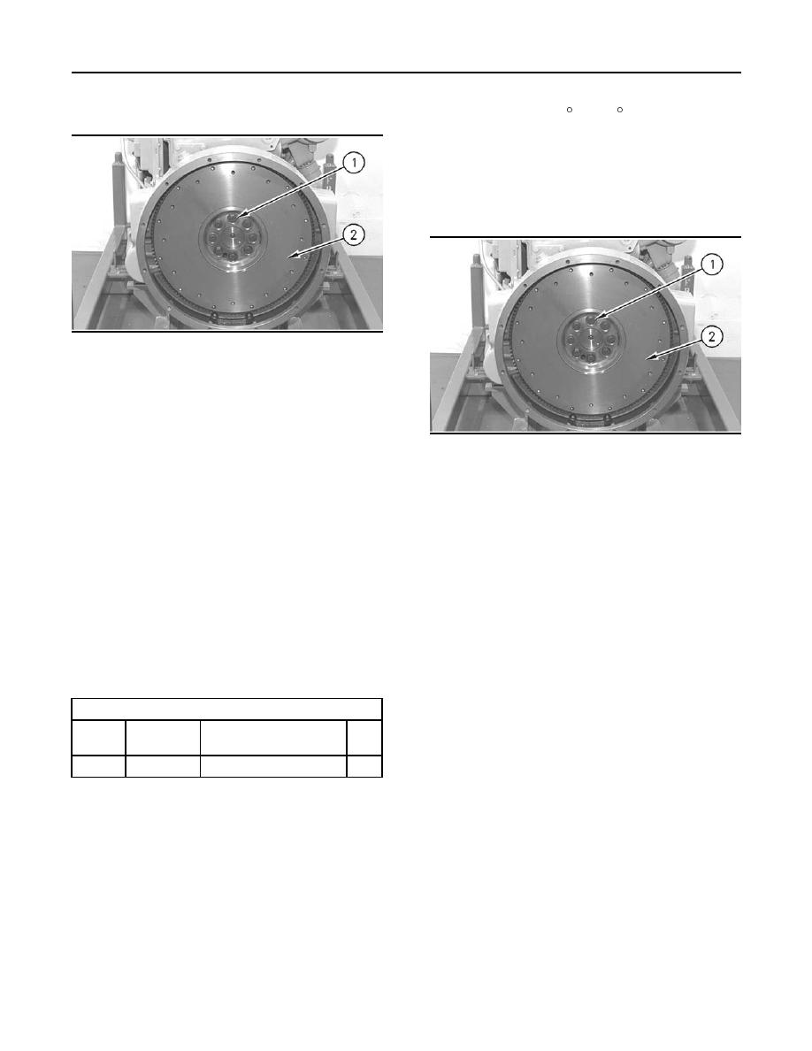
3. Remove top bolt (1) and the washers. Install a
guide bolt that is longer than top bolt (1). Remove
seven remaining bolts (1) and the washers.
4. Remove flywheel (2) from the guide bolt. The
g00613482
weight of flywheel (2) is approximately 23 kg
Illustration 128
(50 lb).
2. Install Tooling (A) on flywheel (2). Fasten a
suitable lifting device to flywheel (2).
5. Inspect the flywheel ring gear. Replace the ring
gear, if necessary. Place the flywheel on a wood
3. Place flywheel (2) in the original position on the
block. Use a hammer and a punch in order to
guide bolt. Align the arrows on flywheel (2) and
remove the flywheel ring gear.
the crankshaft.
i01747268
4. Apply 9S-3263 Thread Lock Compound to the
Flywheel - Install
threads of eight bolts (1).
5. Install seven bolts (1) and the washers. Remove
SMCS Code: 1156-012
the guide bolt and install remaining bolt (1) and
the washer. Tighten the bolts evenly to a torque
Installation Procedure
of 120 20 Nm (90 15 lb ft).
Table 24
6. Check the flywheel runout. Refer to Testing and
Adjusting, "Flywheel - Inspect" for the correct
Required Tools
procedure.
Part
Tool
Part Description
Qty
Number
2
138-7573
A
Link Bracket
Note: Drill and tap the new flywheel ring gear if the
outer bolt holes of the flywheel are used . Use the
flywheel as a template and drill twelve holes to a
diameter of 8.2 mm (0.32 inch). Thread the holes
with a tap.
|
|
Privacy Statement - Press Release - Copyright Information. - Contact Us |
