 |
|||
|
|
|||
|
Page Title:
Test Step 3. Test the Lamp Circuit |
|
||
| ||||||||||
|
|
 423
TM 9-2320-312-24-2
Troubleshooting Section
Not OK The lamp does not turn on. Proceed
Expected Result:
to Test Step 3.
Result 1 The warning lamp turns on while the
Not OK The lamp stays on.
jumper is connected to both sockets. Also, the
warning lamp turns off when the jumper is removed
from one of the sockets.
Repair: Perform the following diagnostic
procedure:
Result 2 The lamp does not turn on while the
jumper is connected to both sockets.
Use ET to determine if an "Engine Monitoring"
condition is causing the lamp to turn on. If an
Result 3 The lamp will stay on while the ECM
"Engine Monitoring" condition is not present,
vehicle harness connector is disconnected.
perform the following diagnostic procedure.
Proceed to Test Step 3.
Results:
Test Step 3. Test the Lamp Circuit.
Result 1 The warning lamp circuit is functioning
properly. Proceed to Test Step 4.
Result 2 The lamp did not turn on. The vehicle's
lamp circuit is not functioning properly. The lamp
is probably burned out or there is a problem in
the wiring from the cab to either the ECM or the
+battery connection. Repair the lamp circuit or
send the vehicle to the OEM dealer for repairs.
STOP.
Result 3
Repair: Perform the following diagnostic
procedure:
The circuit between the ECM and the lamp is
shorted to chassis ground. Repair the circuit or
send the vehicle to the OEM dealer for repairs.
STOP.
Test Step 4. Check ECM Operation of the
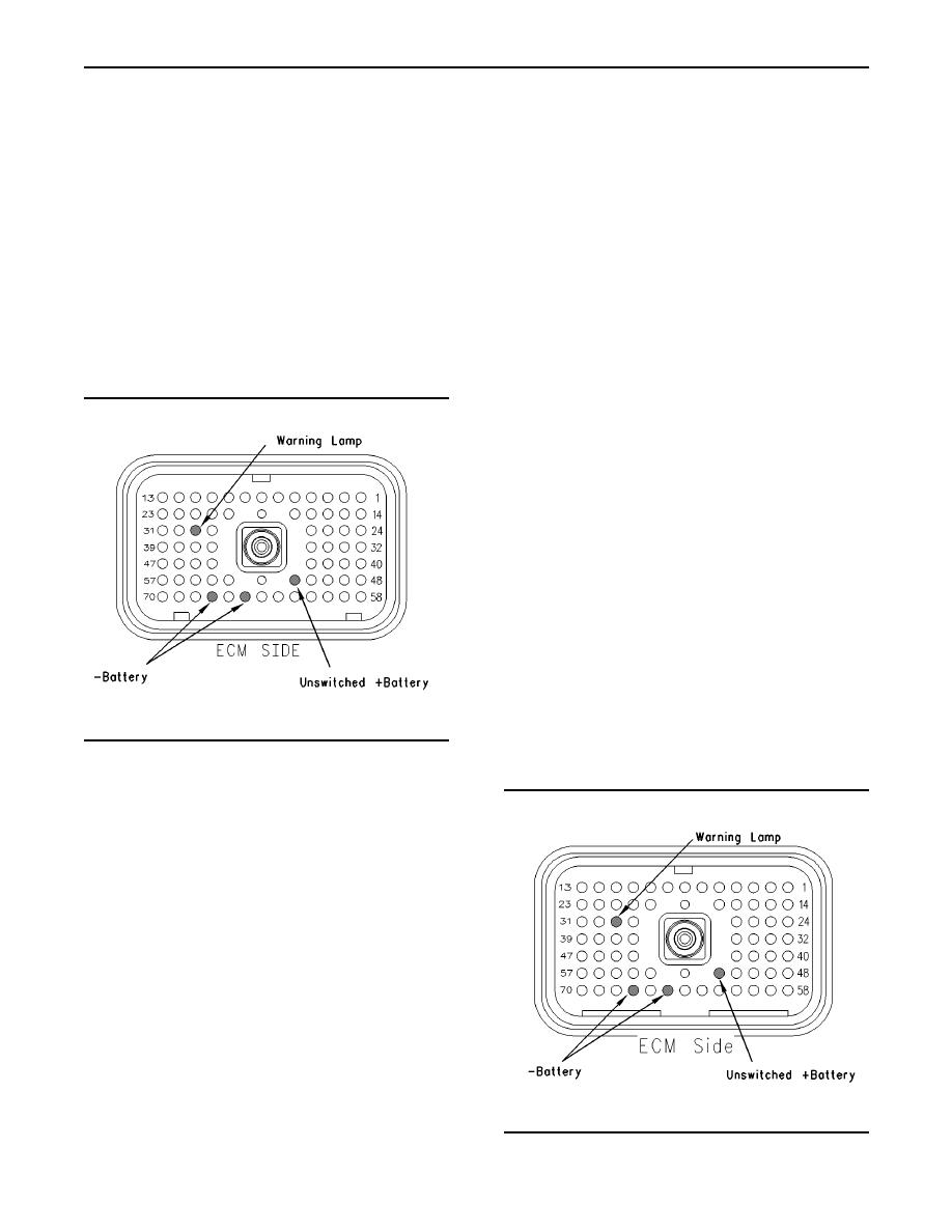
g00769361
Illustration 195
Warning Lamp.
Vehicle harness connector P1
A. Disconnect ECM vehicle harness connector
J1/P1.
B. Fabricate a jumper wire 100 mm (4 inch) long.
Crimp a Deutsch pin to both ends of the wire.
C. Insert the jumper into terminal 29 (warning lamp)
of connector P1. The jumper can be inserted
into the following terminals in order to test the
appropriate lamp circuit:
D. Connect the other side of the jumper wire to P1
terminal 65 (-battery).
E. Turn the ignition key switch to the ON position.
F. While the lamp is being watched, insert the
jumper wire and remove the jumper wire.
Refer to Illustration 195.
g00769368
Illustration 196
ECM breakout T-connector
|
|
Privacy Statement - Press Release - Copyright Information. - Contact Us |
