 |
|||
|
|
|||
|
|
|||
| ||||||||||
|
|
 418
TM 9-2320-312-24-2
Troubleshooting Section
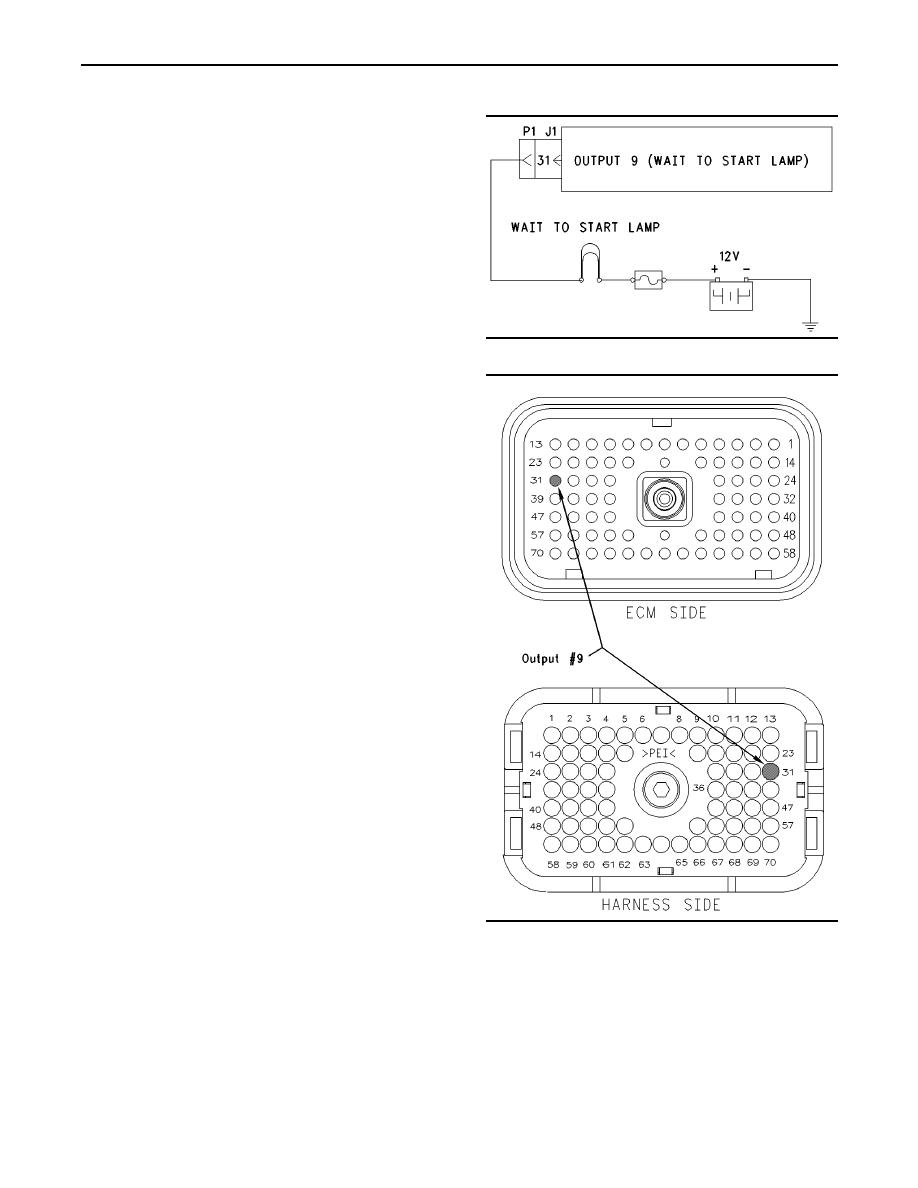
The output 9 (terminal 31) can be used as a fast idle
lamp or a Wait to Start Lamp output. The "Output
#9" parameter defaults to "Fast Idle Lamp", but the
parameter can be programmed to operate as a wait
to start lamp.
Note: When the "Truck Manufacturer" is programmed
to "GM" configurations the "Output #9" parameter is
unavailable. The "Output #9" parameter functions
as fast idle lamp output.
If the "Output #9" parameter is programmed to
"Wait To Start Lamp", the ECM will turn on output 9
when the air inlet heater is operating and the engine
is not running. The wait to start lamp functions
g00770585
Illustration 189
similarly to the lamp for the air inlet heater that can
be installed in parallel with the relay for the air inlet
heater circuit. The wait to start lamp illuminates only
when the engine is not running. The lamp for the
air inlet heater illuminates when the relay for the air
inlet heater is energized.
OCT01 Software
The parameter "Output #9" is no longer available.
The parameter "Wait To Start Lamp" can be
programmed to "J1/P1:31" or "None". When the
parameter is programmed to "J1/P1:31" a lamp
circuit can be connected to terminal 31 in order to
indicate that the air inlet heater is on and the engine
is not running. The parameter "Fast Idle Enabled
Lamp" must be programmed to "J1/P1:21" for this
feature to be used.
Note: This feature is only available when "Truck
Manufacturer" is programmed to "Other".
Electrical Connection of Lamps
One terminal of the lamp must be connected to
battery voltage through the vehicle wiring. The other
terminal is connected to the ECM at the vehicle
harness connector J1/P1 at terminal 31.
The ECM provides a path to ground in order to turn
on the lamp.
g00770189
Illustration 190
Test Step 1. Inspect Electrical Connectors
and Wiring.
A. Thoroughly inspect ECM vehicle harness
connector J1/P1, the firewall bulkhead connector,
or the wait to start lamp. Refer to Troubleshooting,
"Electrical Connectors - Inspect" for details.
|
|
Privacy Statement - Press Release - Copyright Information. - Contact Us |
