 |
|||
|
|
|||
|
Page Title:
Test Step 4. Check the ECM Tachometer Signal |
|
||
| ||||||||||
|
|
 403
TM 9-2320-312-24-2
Troubleshooting Section
Test Step 4. Check the ECM Tachometer
Signal.
g00649125
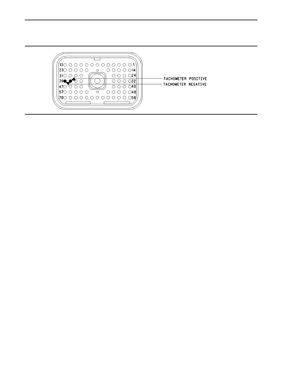
Illustration 177
ECM Breakout T-connector
Note: Performing certain steps within this procedure
Results:
requires the use of a multimeter that is capable of
OK The ECM tachometer output is OK. Connect
measuring a PWM Duty Cycle.
the ECM vehicle harness connector J1 to P1.
A. Disconnect ECM vehicle harness connector
Proceed to Test Step 6.
J1/P1.
Not OK The duty cycle is out of the range.
B. Connect a breakout T to ECM vehicle harness
connector P1.
Repair: Perform the following repair:
C. Fabricate two jumper wires 100 mm (4 inch) long.
1. Temporarily connect a test ECM.
Crimp a Deutsch Pin to one end of each wire.
D. Insert one of the jumper wires into P1:39
(Tachometer-) of the breakout T and insert the
3. Recheck the system for active diagnostic
other jumper wire into P1:38 (Tachometer+) of
codes.
the Breakout T.
4. Repeat the test step.
Refer to Illustration 177.
5. If the problem is resolved with the test ECM,
reconnect the suspect ECM.
following display screens in order:
6. If the problem returns with the suspect ECM,
"Diagnostics"
replace the ECM.
"Diagnostic Tests"
7. Verify that the repair eliminates the problem.
"Special Test"
STOP.
Test Step 5. Inspect the Tachometer
Calibration.
wire from P1:38.
G. Attach the other multimeter lead to the jumper
A. Determine the tachometer engine speed
wire from P1:39.
calibration setting in pulses per revolution. You
may be required to contact the OEM dealer or
you may be required to send the vehicle to the
observe the reading on the multimeter.
OEM dealer for this information.
Expected Result:
B. Connect the electronic service tool at the cab
data link connector.
The multimeter indicates a duty cycle from 30
to 70 percent from each of the terminals for the
tachometer while the engine is running.
on the Customer Parameters screen.
|
|
Privacy Statement - Press Release - Copyright Information. - Contact Us |
