 |
|||
|
|
|||
|
Page Title:
Test Step 1. Inspect Electrical Connectors and Wiring |
|
||
| ||||||||||
|
|
 368
TM 9-2320-312-24-2
Troubleshooting Section
g00642018
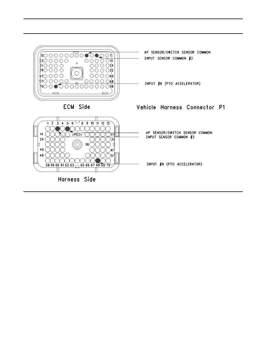
Illustration 165
Terminal locations for ECM
Test Step 1. Inspect Electrical Connectors
E. Check the harness and wiring for abrasion and
and Wiring
pinch points from the remote accelerator position
sensor to the ECM.
A. Connect ET to the cab data link connector. Verify
Expected Result:
that the parameter for the PTO Configuration is
programmed to the "Remote Throttle".
All connectors, pins and sockets should be
completely coupled and/or inserted and the harness
B. Thoroughly inspect ECM vehicle harness
and wiring should be free of corrosion, abrasion
connector J1/P1, the firewall bulkhead connector
or pinch points.
and the connector for the remote accelerator
position sensor. Refer to Troubleshooting,
Results:
"Electrical Connectors - Inspect" for details.
OK Proceed to Test Step 2.
C. Perform a 45 N (10 lb) pull test on each of the
wires in the ECM connector that are associated
Not OK
with the remote accelerator position sensor:
J1/P1:68
Repair: Perform the following diagnostic
procedure:
D. Check the ECM connector (Allen Head Screw)
for the proper torque of 6.0 Nm (55 lb in).
|
|
Privacy Statement - Press Release - Copyright Information. - Contact Us |
