 |
|||
|
|
|||
|
Page Title:
Test Step 3. Inspect Electrical Connectors and Wiring |
|
||
| ||||||||||
|
|
 356
TM 9-2320-312-24-2
Troubleshooting Section
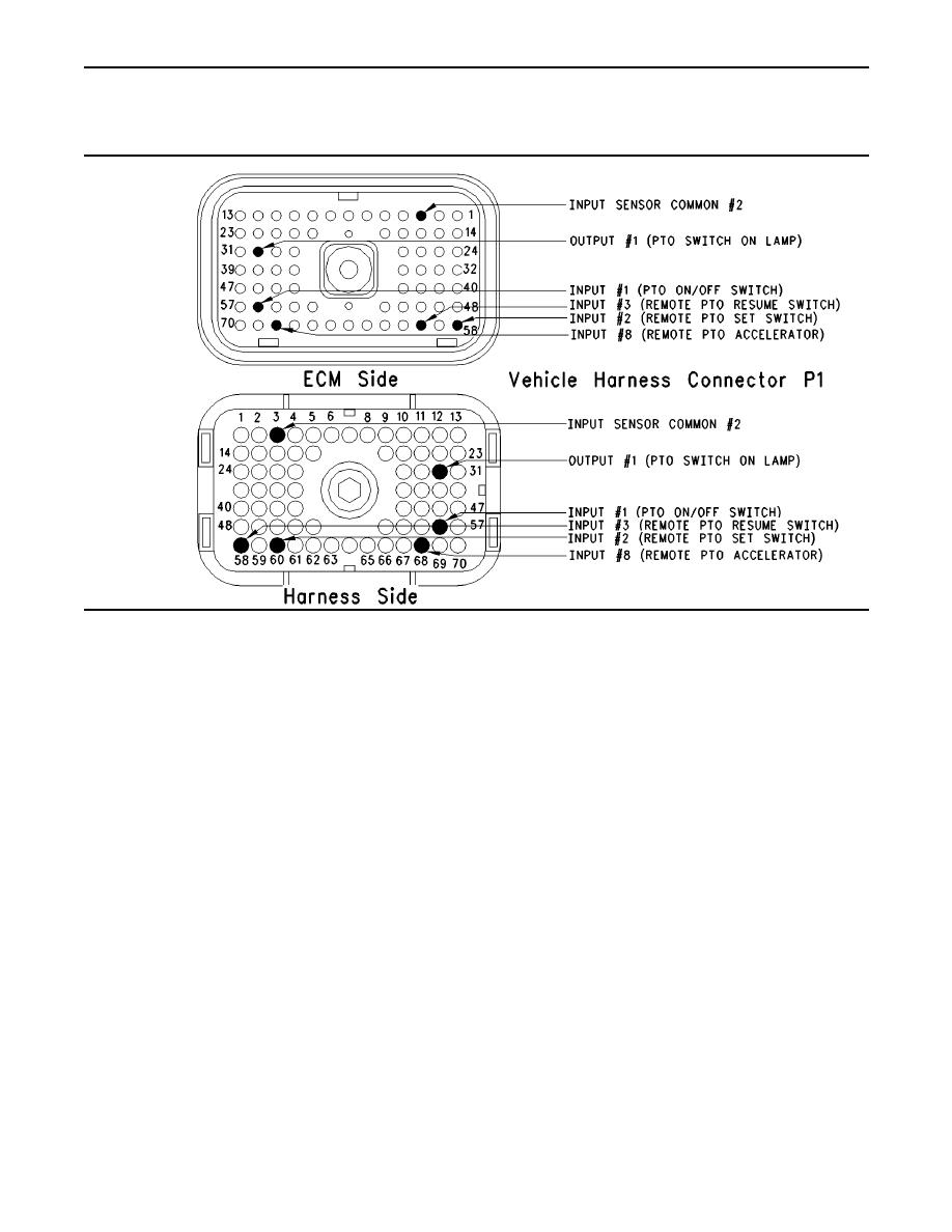
Test Step 3. Inspect Electrical Connectors
and Wiring.
g00713728
Illustration 155
Terminal locations for ECM
terminal 68
A. Thoroughly inspect ECM connector J1/P1,
the firewall bulkhead connectors, and any
connectors that are used by the PTO.
Refer to Illustration 155.
Refer to Troubleshooting, "Electrical Connectors
C. Check the ECM connector (allen head screw) for
- Inspect" for details.
the proper torque of 6.0 nm (55 lb in).
B. Perform a 45 N (10 lb) pull test on each of the
D. Check the harness and wiring for abrasion and
wires in the ECM connector that are associated
pinch points from the sensor to the ECM.
with the connections for the PTO. The following
connections should be tested if the connections
Expected Result:
are used:
All connectors, pins and sockets should be
terminal 3
completely coupled and/or inserted and the harness
and wiring should be free of corrosion, abrasion
terminal 5
or pinch points.
terminal 30
Results:
terminal 35
OK Proceed to Test Step 4.
terminal 44
Not OK
terminal 56
Repair: Perform the following diagnostic
procedure:
terminal 58
terminal 60
|
|
Privacy Statement - Press Release - Copyright Information. - Contact Us |
