 |
|||
|
|
|||
|
Page Title:
Test Step 1. Inspect Electrical Connectors and Wiring |
|
||
| ||||||||||
|
|
 347
TM 9-2320-312-24-2
Troubleshooting Section
Test Step 1. Inspect Electrical Connectors
Expected Result:
and Wiring
All connectors, pins, and sockets are completely
coupled and/or inserted, and the harness and
wiring should be free of corrosion, abrasion or pinch
points.
Results:
OK Proceed to Test Step 2.
Not OK Repair the wiring and connectors or
replace the wiring or the connectors. Ensure that
all of the seals are properly connected. Verify that
the repair eliminates the problem. STOP.
Test Step 2. Check the Switch Status on
ET
A. Connect Electronic Technician (ET) to the cab
data link connector.
B. Turn the ignition key switch to the ON position.
C. Operate the switch in the ON position and the
OFF position.
D. View the switch status on ET.
E. If the switch status indicates "Not Installed", the
parameter "PTO Engine Shutdown Switch" has
not been programmed.
Expected Result:
The status screen should indicate "ON" if the switch
is turned ON. The status screen should indicate
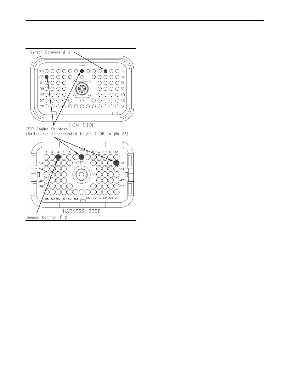
g00839590
Illustration 150
"OFF" if the switch is OFF.
Terminal locations for P1 connector
Results:
A. Thoroughly inspect the ECM vehicle harness
connector J1/P1, the connectors, and the firewall
Yes The switch is operating normally. Continue
bulkhead connectors. Refer to Troubleshooting,
troubleshooting if the original condition is not
"Electrical Connectors - Inspect" for details.
resolved. STOP.
B. Perform a 45 N (10 lb) pull test on each of the
No The ECM is not reading the change in the
wires in the ECM connector that are associated
status of the switch. Proceed to Test Step 3.
with the suspect switch circuit.
C. Check the ECM connector (allen head screw) for
the proper torque of 6.0 Nm (55 lb in).
D. Check the harness and the wiring for abrasion
and for pinch points from the battery to the ECM.
Then, check from the ignition key switch to the
ECM.
Refer to Illustration 150 for terminal locations
for the ECM.
|
|
Privacy Statement - Press Release - Copyright Information. - Contact Us |
