 |
|||
|
|
|||
|
Page Title:
Test Step 1. Inspect Electrical Connectors and Wiring |
|
||
| ||||||||||
|
|
 322
TM 9-2320-312-24-2
Troubleshooting Section
g00728814
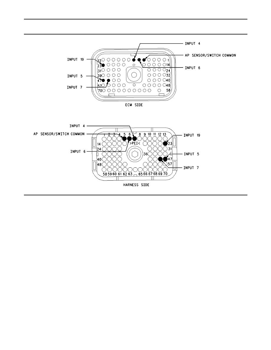
Illustration 141
Terminal Locations for ECM
Test Step 1. Inspect Electrical Connectors
Expected Result:
and Wiring
All connectors, pins, and sockets are completely
coupled and/or inserted, and the harness and
A. Thoroughly inspect the ECM vehicle harness
wiring should be free of corrosion, abrasion or pinch
connector J1/P1, the connectors, and the firewall
points.
bulkhead connectors. Refer to Troubleshooting,
"Electrical Connectors - Inspect" for details.
Results:
B. Perform a 45 N (10 lb) pull test on each of the
OK Proceed to Test Step 2.
wires in the ECM connector that are associated
with the suspect switch circuit.
Not OK Repair the wiring and connectors or
replace the wiring or the connectors. Ensure that
C. Check the ECM connector (allen head screw) for
all of the seals are properly connected. Verify that
the proper torque of 6.0 Nm (55 lb in).
the repair eliminates the problem. STOP.
D. Check the harness and the wiring for abrasion
Test Step 2. Check the Switch Status on
and for pinch points from the battery to the ECM.
an Electronic Service Tool
Then, check from the ignition key switch to the
ECM.
A. Connect the electronic service tool to the cab
Refer to Illustration 141 for terminal locations
data link connector.
for the ECM.
B. Turn the ignition key switch to the ON position.
|
|
Privacy Statement - Press Release - Copyright Information. - Contact Us |
