 |
|||
|
|
|||
|
Page Title:
Test Step 1. Check The Electrical Connectors and The Wiring |
|
||
| ||||||||||
|
|
 275
TM 9-2320-312-24-2
Troubleshooting Section
Test Step 1. Check The Electrical
Expected Result:
Connectors and The Wiring
The status screen should indicate "ON" if the switch
is turned on. The status screen should indicate
A. Thoroughly inspect the ECM vehicle harness
"OFF" if the switch is off.
connector J1/P1, terminal 40, and the firewall
bulkhead connectors. Refer to Troubleshooting,
Results:
"Inspecting Electrical Connectors" for details.
YES The switch is operating normally. Continue
B. Perform a 45 N (10 lb) pull test on each of the
troubleshooting if the original condition is not
wires in the ECM connector that are associated
resolved. STOP.
with the fast idle switch circuit.
NO The ECM is not reading the "Switch Status"
The wires are on the following terminals:
change. Proceed to Test Step 3.
terminal 40
Test Step 3. Check The Switch Circuit for
the ECM.
terminal 5
C. Check the ECM connector (allen head screw) for
the proper torque of 6.0 Nm (55 lb in).
D. Check the harness and the wiring for abrasion
and pinch points from the battery to the ECM.
Then, check from the ignition key switch to the
ECM.
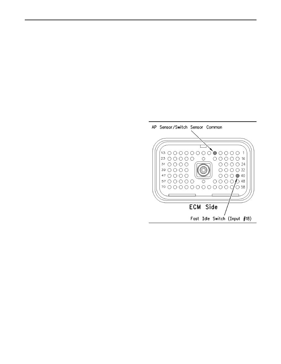
Refer to Illustration 107 for terminal locations
for the ECM.
Expected Result:
All connectors, pins, and sockets are completely
coupled and/or inserted, and the harness and
wiring should be free of corrosion, abrasion or pinch
points.
Results:
OK Proceed to Test Step 2.
g00770457
Illustration 108
Not OK Repair the wiring and connectors or
A. Turn the ignition key switch to the OFF position.
replace the wiring or the connectors. Ensure that
all of the seals are properly connected. Verify that
B. Install a 70 terminal breakout T to the ECM
the repair eliminates the problem. STOP.
vehicle harness connector J1/P1.
Test Step 2. Check the Status of the Fast
C. Fabricate a jumper wire 100 mm (4 inch) long.
Idle Switch On The Electronic Service
Crimp a Deutsch pin to both ends of the wire.
Tool.
D. Insert the jumper wire into terminal 40 of the
A. Connect an Electronic Service Tool at the cab
breakout T. Connect the other end of the jumper
data link connector.
wire to terminal 5 in the breakout T. Terminal 5 is
AP sensor/switch common.
B. Turn the ignition key switch to the ON position.
E. Connect an Electronic Service Tool at the cab
C. Operate the switch in the ON position and the
data link connector.
OFF position.
F. Turn the ignition key switch to the ON position.
D. View the "Fast Idle Switch" status on the
Electronic Service Tool.
G. Alternately remove the jumper wire and then
insert the jumper wire from terminal 5. At the
Note: A fast idle rpm must be programmed in order
same time, monitor the "Status Screen" on the
to automatically go to a set speed.
Electronic Service Tool.
|
|
Privacy Statement - Press Release - Copyright Information. - Contact Us |
