 |
|||
|
|
|||
|
Page Title:
Test Step 1. Inspect Electrical Connectors and Wiring |
|
||
| ||||||||||
|
|
 253
TM 9-2320-312-24-2
Troubleshooting Section
Results:
OK Proceed to Test Step 2.
Not OK
Repair: Perform the following repair:
Repair the connectors or wiring and/or replace
the connectors or wiring. Ensure that all of the
seals are properly in place and ensure that the
connectors are completely coupled.
Verify that the repair eliminates the problem.
STOP.
Test Step 2. Use ET to Check the Relay.
A. Turn the ignition key switch to the ON position.
B. Access the special test"Engine Running Output"
on ET. The "Engine Running Output" test will
enable the engine running output when the test
is active.
C. Begin the "Engine Running Output" test and
listen for the relay to "click". You may need to be
near the engine in order to hear the "click".
Expected Result:
The relay activates when the special test is enabled.
Results:
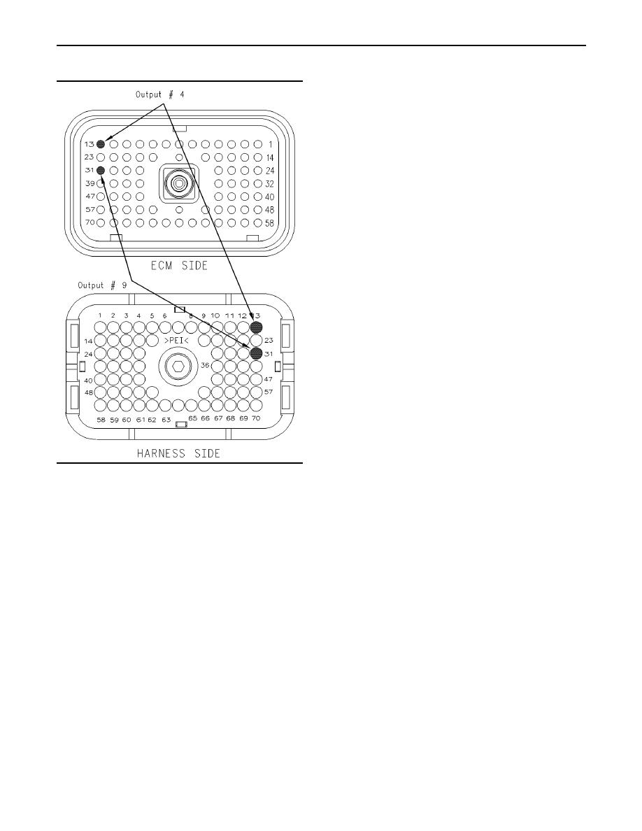
g00832305
Illustration 89
Location for the ECM terminal
Yes The ECM and vehicle components are
operating correctly. STOP.
Test Step 1. Inspect Electrical Connectors
and Wiring.
No Proceed to Test Step 3.
A. Thoroughly inspect ECM vehicle harness
Test Step 3. Use ET to Check the ECM.
connector J1/P1, and the firewall bulkhead
connector.
A. Connect ET to the cab data link connector.
Refer to Troubleshooting, "Electrical Connectors
B. Turn the ignition key switch to the OFF position.
- Inspect" for details.
C. Disconnect the ECM vehicle harness connector
B. Perform a 45 N (10 lb) pull test on terminal 13
J1/P1.
in the ECM connector.
D. Connect a breakout T between ECM
C. Check the ECM connector (allen head screw) for
connectorsJ1 and P1.
the proper torque of 6.0 Nm (55 lb in).
E. Connect a voltage test lamp to terminal 13
D. Check the harness and wiring for abrasion and
(Output 4) and terminal 65 (-battery) of the
for pinch points from the sensor to the ECM.
breakout T.
Expected Result:
Note: If the vehicle is a GM-560 application, connect
the voltage test lamp to terminal 31 (Output 9) and
All connectors, pins and sockets should be
terminal 65 (-battery) of the breakout T.
completely coupled and/or inserted and the harness
and wiring should be free of corrosion, abrasion
F. Turn the ignition key switch to the ON position.
or pinch points.
|
|
Privacy Statement - Press Release - Copyright Information. - Contact Us |
