 |
|||
|
|
|||
|
Page Title:
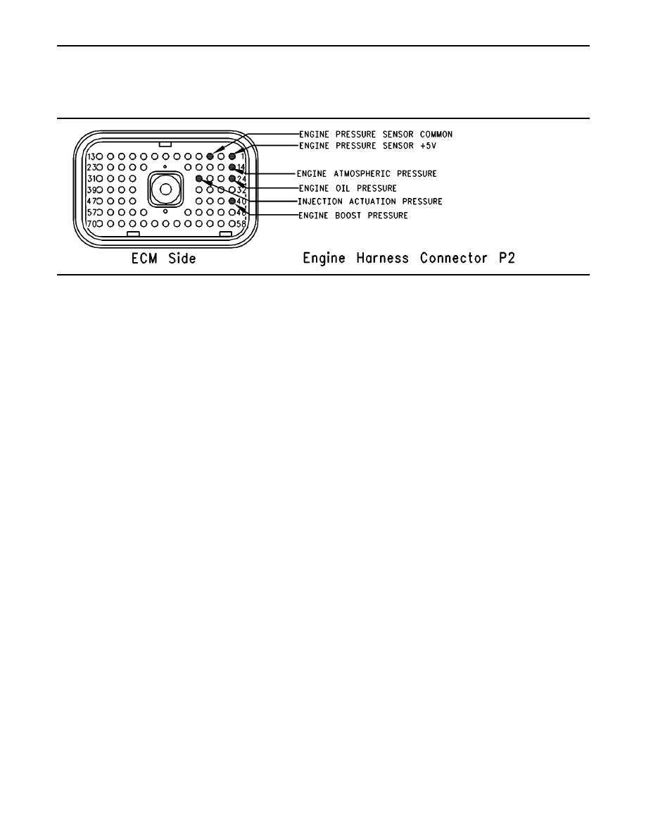
Illustration 86 Engine harness connector P2 |
|
||
| ||||||||||
|
|
 250
TM 9-2320-312-24-2
Troubleshooting Section
Test Step 9. Check the Operation of the
ECM by Creating Open and Short Circuits
at the ECM Connector.
g00741957
Illustration 86
Engine harness connector P2
Note: If access to ECM connector J2 is limited, it
A. Turn the ignition key switch to the OFF position.
may be helpful to connect a breakout T to ECM
connector J2 so the jumper wire can be inserted
B. Disconnect ECM engine harness connector
into the breakout T. Ensure that the jumper wire is
J2/P2. Thoroughly inspect both halves of the
inserted into the breakout T and that the full wiring
connector J2/P2 for signs of corrosion or
harness is attached.
moisture.
Refer to Illustration 86 for the engine harness
C. Turn the ignition key switch to the ON position.
connector P2.
Monitor the "Active Diagnostic Code" screen.
Wait at least 15 seconds for activation of the
Expected Result:
code.
Open circuit diagnostic codes and short circuit
An open circuit diagnostic code should be active
diagnostic codes were active.
for the suspect sensor.
Results:
Note: When the engine harness is disconnected, all
of the open circuit diagnostic codes for the pressure
OK The ECM is operating properly. Proceed to
sensors will be active. This is normal. Disregard the
diagnostic codes for the other pressure sensors.
Test Step 10.
Direct your attention to the diagnostic codes for the
Not OK One of the following conditions exists:
suspect sensor only.
The open circuit diagnostic code is not active
D. Turn the ignition key switch to the OFF position.
when the harness is disconnected. The short
circuit diagnostic code is not active when the
E. Fabricate a jumper wire 150 mm (6 inch) long.
jumper wire is installed.
Crimp a Deutsch Socket to both ends of the wire.
Repair: Perform the following repair:
F. Install the jumper wire on the ECM connector
J2. Insert the jumper wire between the terminal
1. Temporarily connect a test ECM.
for the suspect sensor signal and the common
connection for the engine's pressure sensor
(terminal 3).
3. Recheck the system for active diagnostic
A short circuit diagnostic code should be active
codes.
when the jumper wire is installed.
4. Repeat the Test Step.
5. If the problem is resolved with the test ECM,
reconnect the suspect ECM.
|
|
Privacy Statement - Press Release - Copyright Information. - Contact Us |
