 |
|||
|
|
|||
|
Page Title:
Test Step 9. Disconnect the Coolant Level Sensor and Check the Supply Voltage (+5 VDC) |
|
||
| ||||||||||
|
|
 195
TM 9-2320-312-24-2
Troubleshooting Section
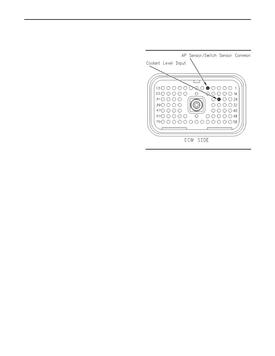
Test Step 10. Disconnect the Terminal
Expected Result:
for the Sensor Supply (+5 VDC) from the
ECM Connector
All connectors, pins and sockets should be
completely coupled and/or inserted and the harness
and wiring should be free of corrosion, abrasion
or pinch points.
Results:
OK Proceed to Test Step 9.
Not OK
Repair: Repair the connectors or wiring and/or
replace the connectors or wiring. Ensure that all
of the seals are properly in place and ensure that
the connectors are completely coupled.
Verify that the repair eliminates the problem. Clear
all diagnostic codes.
STOP.
Test Step 9. Disconnect the Coolant Level
Sensor and Check the Supply Voltage (+5
g00884813
Illustration 59
VDC)
Terminal locations on the breakout T (2-wire float sensor)
A. Turn the ignition key switch to the OFF position.
A. Turn the ignition key switch to the OFF position.
B. Disconnect the coolant level sensor from the
B. Disconnect the ECM vehicle harness connector
harness.
J1/P1.
C. Install a breakout T between ECM vehicle
harness connector.
harness connector J1 and vehicle harness
connector P1.
D. Turn the ignition key switch to the ON position.
D. Turn the ignition key switch to the ON position.
Expected Result:
E. Measure the voltage at the breakout T from
The measured voltage is between 4.5 VDC and 5.5
terminal 26 to terminal 5.
VDC.
Refer to Illustration 59.
Results:
Expected Result:
Yes The correct voltage is reaching the sensor.
The measured voltage is between 4.5 VDC and 5.5
Repair: Replace the sensor.
VDC.
STOP.
Results:
No Proceed to Test Step 10.
Yes The problem is located in the harness
wiring.
Repair: Repair the wiring or replace the wiring,
as required.
Verify that the repair eliminates the problem.
STOP.
No The problem is on the ECM side.
|
|
Privacy Statement - Press Release - Copyright Information. - Contact Us |
