 |
|||
|
|
|||
|
Page Title:
Test Step 8. Inspect Electrical Connectors and Wiring for the 2-Wire Float Sensor |
|
||
| ||||||||||
|
|
 194
TM 9-2320-312-24-2
Troubleshooting Section
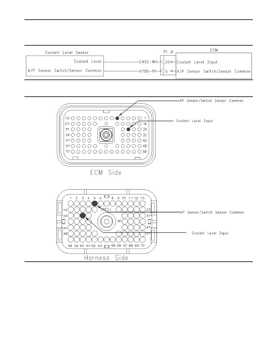
Test Step 8. Inspect Electrical Connectors
and Wiring for the 2-Wire Float Sensor
g00882602
Illustration 57
Schematic for 2-wire float sensor
g00884766
Illustration 58
Terminal locations for ECM connector P1 (2-wire float sensor)
P1/J1:26 coolant level input
A. Thoroughly inspect ECM vehicle harness
connector J1/P1, the connector for the
P1/J1:5 AP sensor/switch sensor common
coolant level sensor and the terminals for the
coolant level sensor in the connectors. Refer
to Troubleshooting, "Electrical Connectors -
Refer to Illustration 58.
Inspect" for details.
C. Check the ECM connector (allen head screw) for
B. Perform a 45 N (10 lb) pull test on each of the
the proper torque of 6.0 Nm (55 lb in).
wires in the ECM connector that are associated
with the following connections:
D. Check the harness and wiring for abrasion and
pinch points from the sensor to the ECM.
|
|
Privacy Statement - Press Release - Copyright Information. - Contact Us |
